Fluid distribution system

a fluid distribution system and fluid technology, applied in water cleaning, sewage draining, agriculture, etc., can solve the problems of increasing the cost of septic system installation, prior art constructions have not met consumer demand, and the system is not highly effective, convenient to install, efficient and competitively priced, etc., to achieve efficient cleaning action

Active Publication Date: 2010-07-27
BURRITT WAYNE +2
View PDF4 Cites 3 Cited by
  • Summary
  • Abstract
  • Description
  • Claims
  • Application Information

AI Technical Summary

Benefits of technology

[0015]Another object of the present invention is to “kickstart” the working of the system by spraying an enzyme enriched solution directly to the cardboard. The bacteria attracted by the glucose in the cardboard quickly form an efficient biomat in the void, resulting in a very efficient cleaning action especially useful in waterside locations.

Problems solved by technology

In spite of the industry needs for improved underground fluid distribution systems, prior art systems have failed to provide highly effective, easily installed, efficient and competitively priced systems.
In view of new standards and governmental oversight in protecting rivers, streams, and groundwater supplies, consumers' cost for the installation of a new septic system, as well as the repair and / or reconditioning of existing septic systems has been increasing substantially.
In addition, although substantial pressure has been imposed by consumers on more efficient systems and more efficient installation procedures, prior art constructions have failed to meet the consumer demand.
In particular, substantial costs and expenses are incurred in forming the plurality of trenches required for the leaching fields, constructing the trenches to the proper depth, and then filling the trenches with the required materials.
Although some attempts have been made to develop systems that achieve leaching fields in a more efficient manner, these prior art attempts have failed to provide effective systems which are also cost efficient.

Method used


Image

  • Fluid distribution system
  • Fluid distribution system
  • Fluid distribution system

Examples


Embodiment Construction

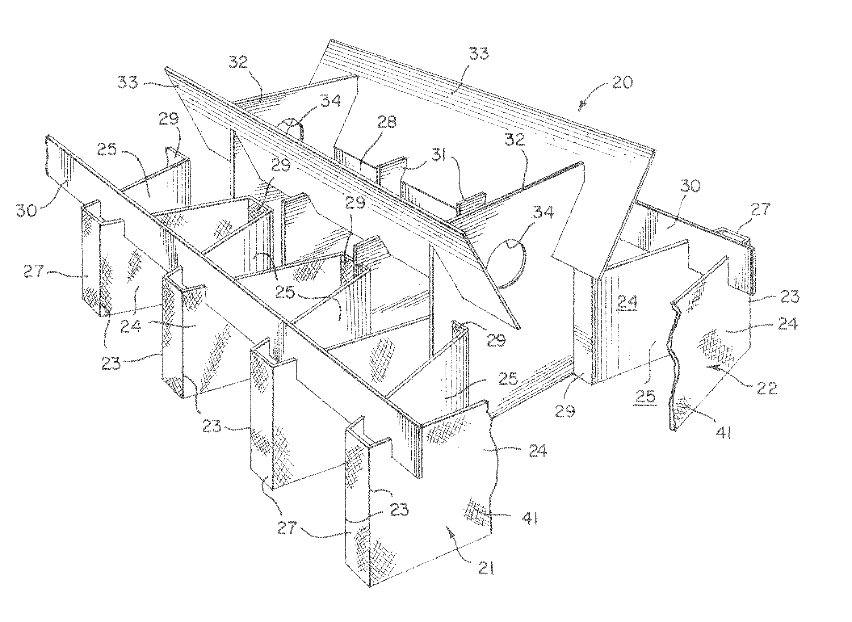
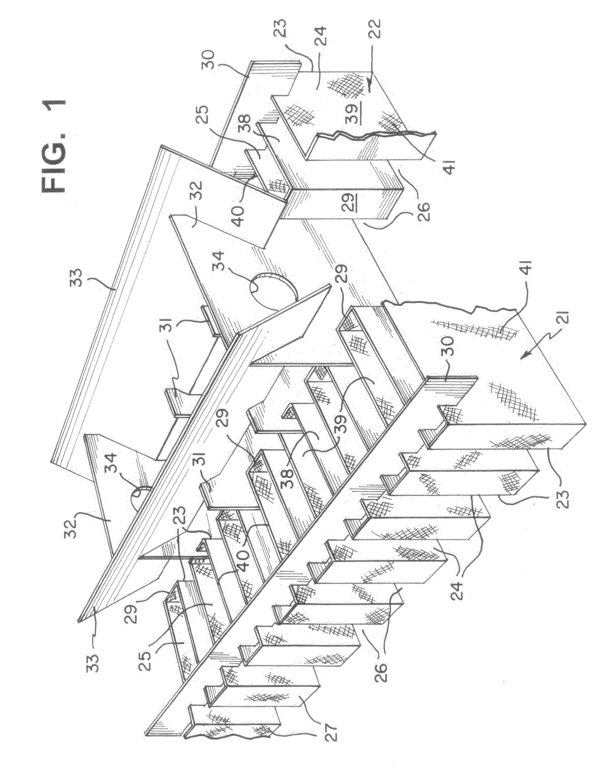
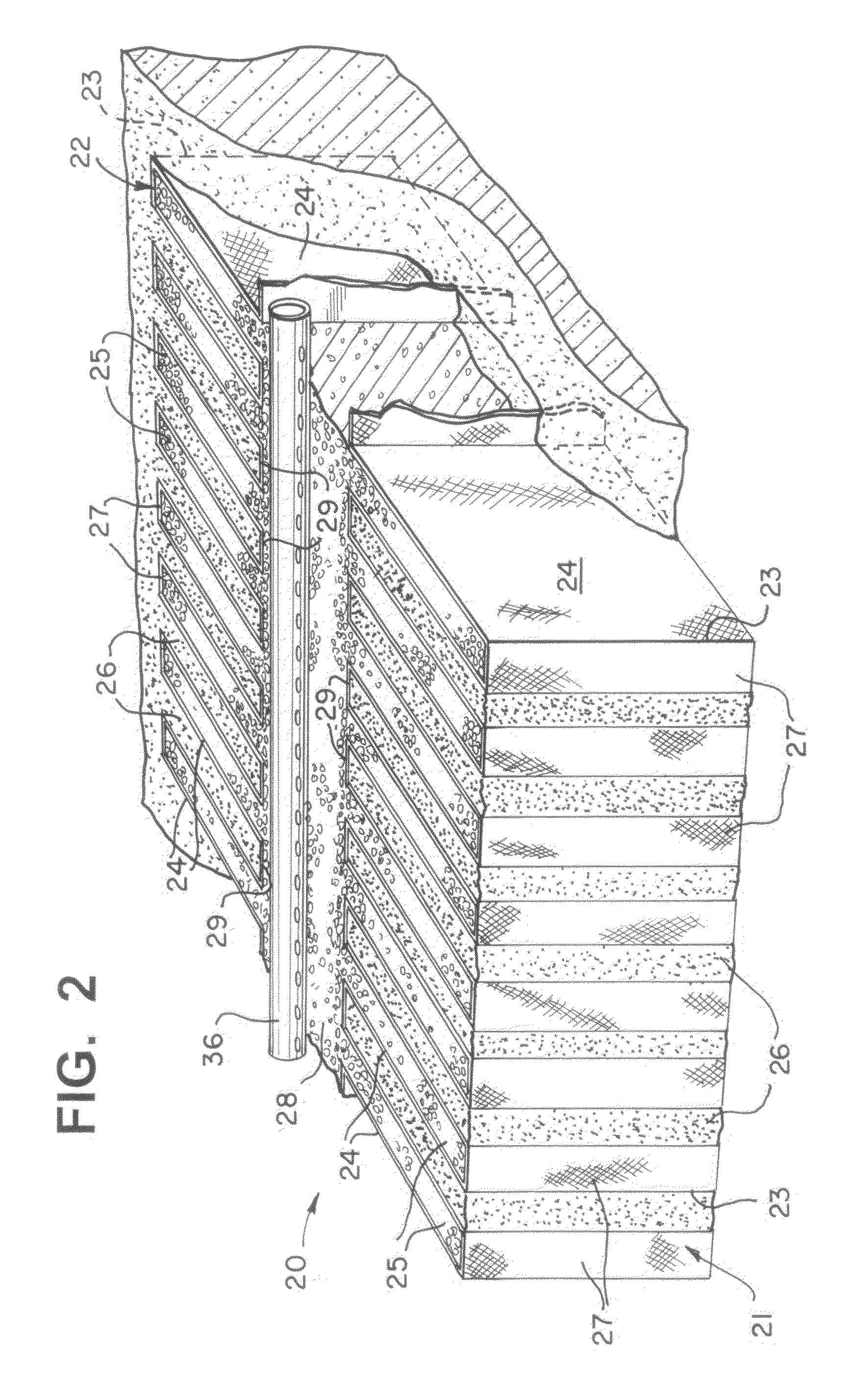
[0042]By referring to FIGS. 1-10, along with the following detailed discussion, the preferred constructions and operation of fluid distribution system 20 of the present invention can best be understood. However, it is also to be understood that alterations and variations can be made in the embodiments detailed herein without departing from the scope of the present invention. Consequently, the embodiments disclosed in FIGS. 1-5 and fully discussed below are provided for exemplary purposes only and are not intended as a limitation of the present invention. Although not shown, it is clearly envisaged that the assembled system can be curved, straight, square, triangular, rectangular, trapezoidal, or a combination of all of these configurations, as well as other configurations.

[0043]As an overview, the present invention provides a flexible system of interlocking corrugated cardboard panels of modular design which when assembled in the field to a state certified engineers or installer's d...


PUM


Abstract

By providing an easily transported, filler component system, leaching field forming elements for establishing a series of flexible design passageways into which the desired fill material is placed, a highly effective, easily installed, competitively priced with enhanced biological habitat underground fluid distribution system is achieved. In accordance with the present invention, the desired passageways are quickly and efficiently created by employing pre-folded cardboard panels, or other pervious materials, placing the materials in an excavated location or site in cooperating relationship with each other for creating the desired leaching fields. In the preferred embodiment, two, substantially identical, pre-folded cardboard panels are employed and are positioned in juxtaposed, cooperating, spaced, facing relationship with each other, establishing a central passageway therebetween.

Description

RELATED DATA[0001]This application is a continuation-in-part patent application of U.S. Ser. No. 11 / 805,915, filed May 25, 2007 for a FLUID DISTRIBUTION SYSTEM which is related to U.S. Provisional Patent Application Ser. No. 60 / 812,028, filed Jun. 7, 2006, entitled FLUID DISTRIBUTION SYSTEM.TECHNICAL FIELD[0002]This invention relates to underground fluid distribution systems and, more particularly to a system of component pieces assembled in underground fluid distribution systems which are compact, permitting installation in smaller areas than other systems and installed in a cost-effective manner and becoming environmentally friendly.BACKGROUND ART[0003]For many years, substantial attention has been devoted to the development of improved underground fluid distribution systems which are capable of effectively treating and handling water, sewage effluent, and other similar liquids in an efficient manner. In particular, the effective and efficient filtration of these liquids is requir...

Claims


Application Information

Patent Timeline
Patent Type & Authority Patents(United States)
IPC IPC(8): E02B11/00E02B15/00
CPCE03F1/002
Inventor BURRITT, WAYNEBUTLER, ROBERTSCHAUB, FRANK A.
Owner BURRITT WAYNE
Why Eureka
Try Eureka