
Method and apparatus for transmitting/receiving feedback information representing channel quality in a MIMO-OFDM system

a channel quality and mimo-ofdm technology, applied in the field of mobile communication systems, can solve the problems of ineffective processing of inability to efficiently feed back channel quality information, and inability to efficiently process a large amount of wireless data

Inactive Publication Date: 2010-07-27
SAMSUNG ELECTRONICS CO LTD
View PDF12 Cites 33 Cited by
  • Summary
  • Abstract
  • Description
  • Claims
  • Application Information

AI Technical Summary

Benefits of technology

This approach effectively reduces the feedback overhead, enhances transmission efficiency, and maintains diversity gains by selecting subbands with optimal channel qualities and using appropriate precoding, resulting in improved SINR and resource allocation without compromising frequency and space diversity.

Problems solved by technology

In contrast, 2nd Generation (2G) and 3rd Generation (3G) mobile communication systems have limitations in fast processing of a wide range of data due to the use of a single transmit / receive antenna.
Compared to OFDM, Code Division Multiple Access (CDMA) supports no more than up to 144 kbps in a mobile environment and is not effective in processing a large amount of wireless data.
However, the MIMO system is vulnerable to Inter-Symbol Interference (ISI) and frequency selective fading involved in high-speed data transmission.
In the nature of using a plurality of transmit / receive antennas, the total amount of channel quality information is very large, thus imposing a large overhead on uplink signaling.
The simplest method for transmitting feedback information in the MIMO-OFDM system is to transmit channel quality information about all subbands or N best subbands, which results in a very large signaling overhead.
Moreover, the third method suffers resource use inefficiency when the channel statuses of adjacent subbands are different.

Method used


Image

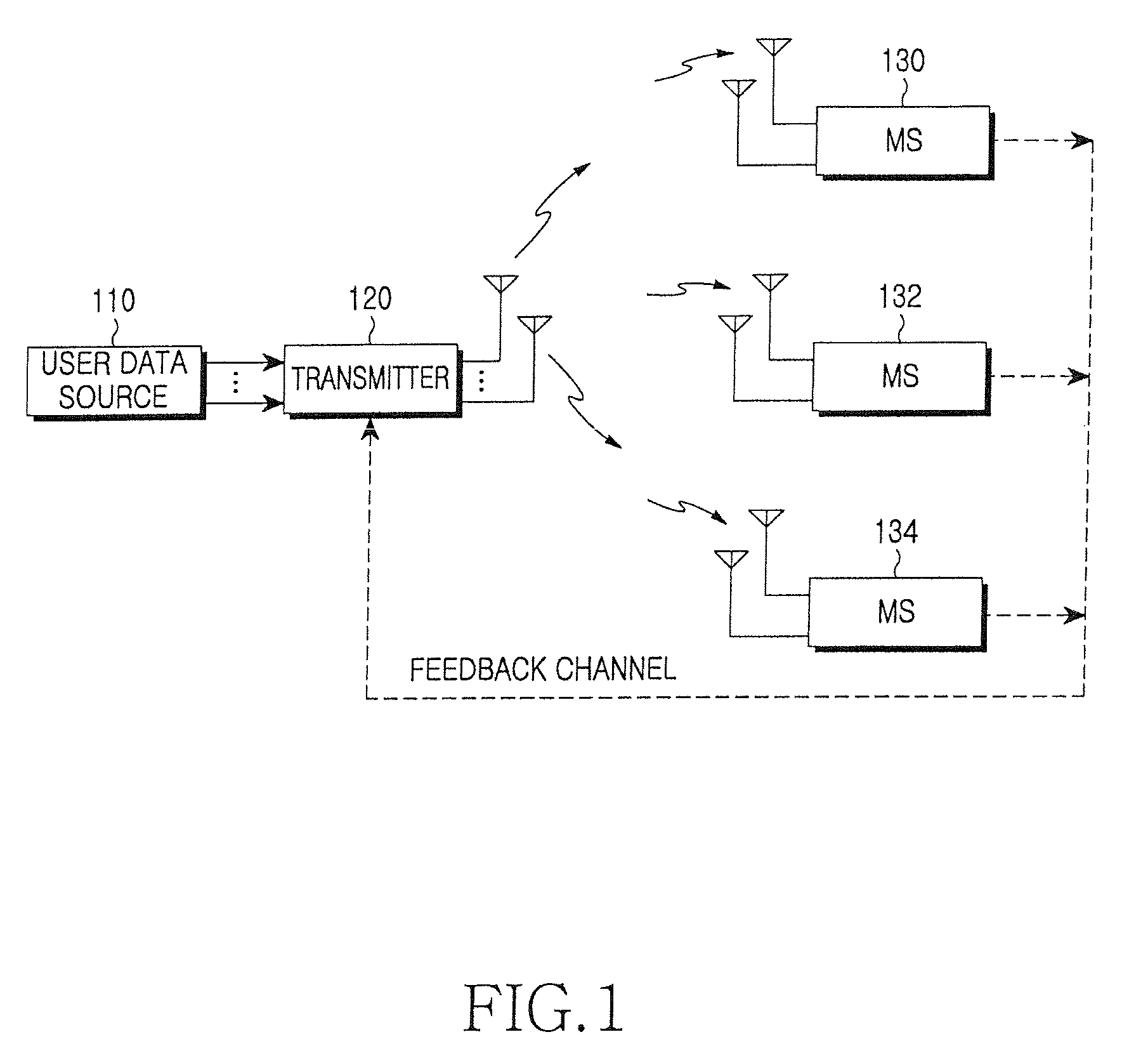
  • Method and apparatus for transmitting/receiving feedback information representing channel quality in a MIMO-OFDM system
  • Method and apparatus for transmitting/receiving feedback information representing channel quality in a MIMO-OFDM system
  • Method and apparatus for transmitting/receiving feedback information representing channel quality in a MIMO-OFDM system

Examples


Embodiment Construction

[0025]Reference will now be made in detail to the present embodiments of the present invention, examples of which are illustrated in the accompanying drawings, wherein like reference numerals refer to the like elements throughout. The embodiments are described below in order to explain the present invention by referring to the figures.

[0026]Exemplary embodiments of the present invention provide a method for transmitting feedback information (i.e. channel quality information) representing downlink channel quality, especially a method for reducing the size of the feedback information in a MIMO-OFDM system.

[0027]In an OFDM system, a total frequency band is divided into a plurality of subbands and the subbands are allocated to individual MSs. Feedback information transmitted from the plurality of MSs to a BS causes a large overhead. Therefore, one task to tackle in the MIMO-OFDM system is to reduce the size of the feedback information.

[0028]An aspect of the present invention makes an ap...


PUM


Abstract

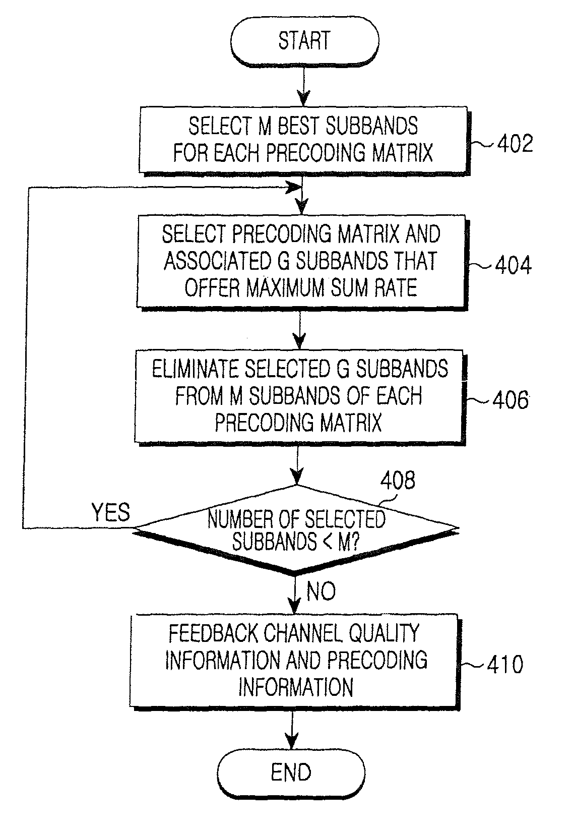
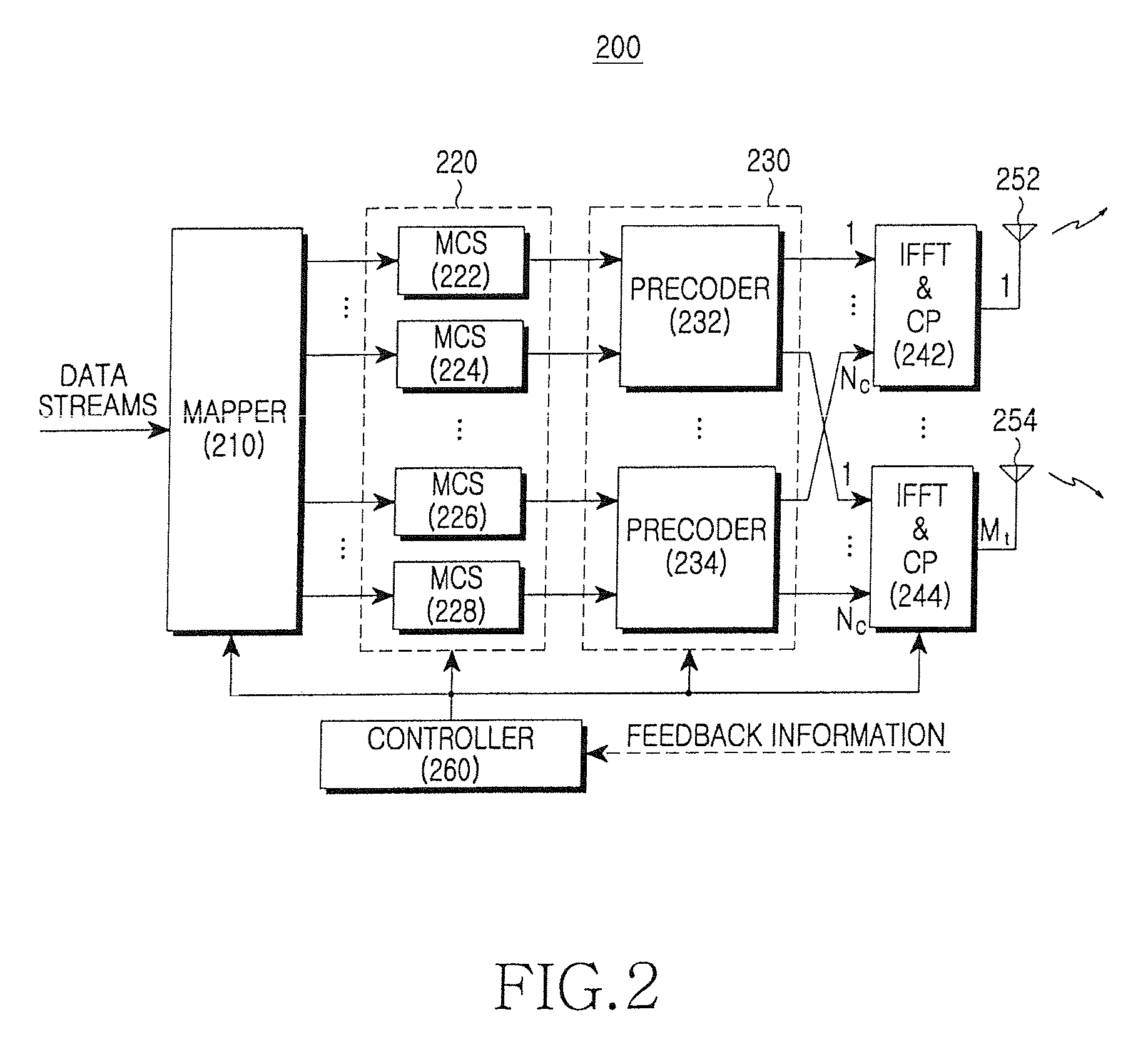
A method of transmitting / receiving feedback information representing channel quality in a MIMO-OFDM system, in which a receiver measures channel qualities of signals transmitted on a plurality of subbands through a plurality of transmitting antennas by a transmitter, selects a predetermined number of subbands having a highest transmission performance based on the measured channel qualities and preceding information, determines at least one subband group with a maximum rate from among the selected subbands and the preceding information associated with the at least one subband group, and transmits feedback information to the transmitter, the feedback information including channel quality information about the at least one subband group and the associated preceding information.

Description

CROSS-REFERENCE TO RELATED APPLICATIONS[0001]This application claims the benefit of Korean Application No. 2006-78339, filed Aug. 18, 2006, in the Korean Intellectual Property Office, the disclosure of which is incorporated herein by reference.BACKGROUND OF THE INVENTION[0002]1. Field of the Invention[0003]An aspect of the present invention generally relates to a mobile communication system. More particularly, an aspect of the present invention relates to a method and apparatus for transmitting / receiving channel quality information in a Multiple Input Multiple Output (MIMO)-Orthogonal Frequency Division Multiplexing (OFDM) mobile communication system.[0004]2. Description of the Related Art[0005]MIMO is essential to enable high-speed mobile data services in a broadband mobile communication system. A MIMO system is an antenna system with multiple inputs and multiple outputs. Since the MIMO system can transmit different information from each antenna, the MIMO system can increase the am...

Claims


Application Information

Patent Timeline
Patent Type & Authority Patents(United States)
IPC IPC(8): H04B1/00H04B7/00H04J99/00H04W28/06
CPCH04B7/0417H04B7/0634H04B7/0639H04B7/066H04L1/0026H04L5/0023H04L5/006H04W28/06H04L1/0003H04L1/0009H04L5/0064H04L25/03343H04L2025/03426H04L2025/03802H04B7/0452
Inventor KIM, SUNG-JINKIM, HO-JINLI, JIANJUNSUH, JUNG-HOONPARK, CHANG-SOON
Owner SAMSUNG ELECTRONICS CO LTD
Learn More