Cage bar comprising a spacer, and pressing device

a cage bar and spacer technology, applied in gravity filters, loose filtering material filters, cartridge filters, etc., can solve the problems of spacers falling out, significant increase production costs, and failure to provide adequate protection by spot welding

Active Publication Date: 2010-08-03
HARBURG FREUDENBERGER MASCHENBAU
View PDF14 Cites 1 Cited by
  • Summary
  • Abstract
  • Description
  • Claims
  • Application Information

AI Technical Summary

Benefits of technology

[0011]The objective of the present invention is to design a press cage bar of the aforementioned type in a way that is conducive to both a high degree of utility and economical manufacturing.
[0013]A further objective of the present invention is to design a device of the aforementioned type in such a way that a high degree of operating reliability is achieved at a favorable manufacturing cost.
[0015]A design that is inexpensive to manufacture and at the same time is highly functional is provided by the combination of the feature of a spacer realized as a deposit weld and the feature of the elongated formation of the deposit weld transversely to the longitudinal direction of the cage bar and by the clearance both between the spacer and the wear surface and between the spacer and the underside of the cage bar. The clearance between the spacer and the hard layer prevents the occurrence of negative effects on the material properties of the hard layer when the spacer is mounted. In particular, it is critical that local heating of the hard layer be prevented, since this can cause stresses, cracking or embrittlement. Furthermore, in the event of clogging or reduction of the cross section of the drainage channels formed between the spacers, the clearances that are provided allow the draining liquid to be conveyed in the area of an adjacent drainage channel. The term liquids is understood to include substances with flowable, pasty or dispersive consistencies.
[0016]In addition, the formation of the spacers as deposit welds produces a strong connection between the spacers and the body of the cage bar, so that the spacers cannot fall off or slip. Due to the increasing thickness of the spacers in the direction extending from the hard layer towards the underside of the cage bar, an angle of inclination of the spacers is produced that allows a plurality of spacers to be positioned with precise fitting along the inner contour of a press drum.
[0018]Providing the end of the spacer that faces the hard layer with a rounded contour also contributes to low flow resistance.

Problems solved by technology

However, due to the considerable forces that act during the pressing operation, these methods of installation of the spacers have the disadvantage that he spacers can be caused to slip, which can result in complete detachment of the cage bars and can cause the spacers to fall out.
The use of spot welding also fails to provide adequate protection against slipping due to the danger of the welds tearing off.
However, in view of the large number of press cage bars that are used, this significantly increases production costs compared to the use of loose spacers.

Method used


Image

  • Cage bar comprising a spacer, and pressing device
  • Cage bar comprising a spacer, and pressing device
  • Cage bar comprising a spacer, and pressing device

Examples


Embodiment Construction

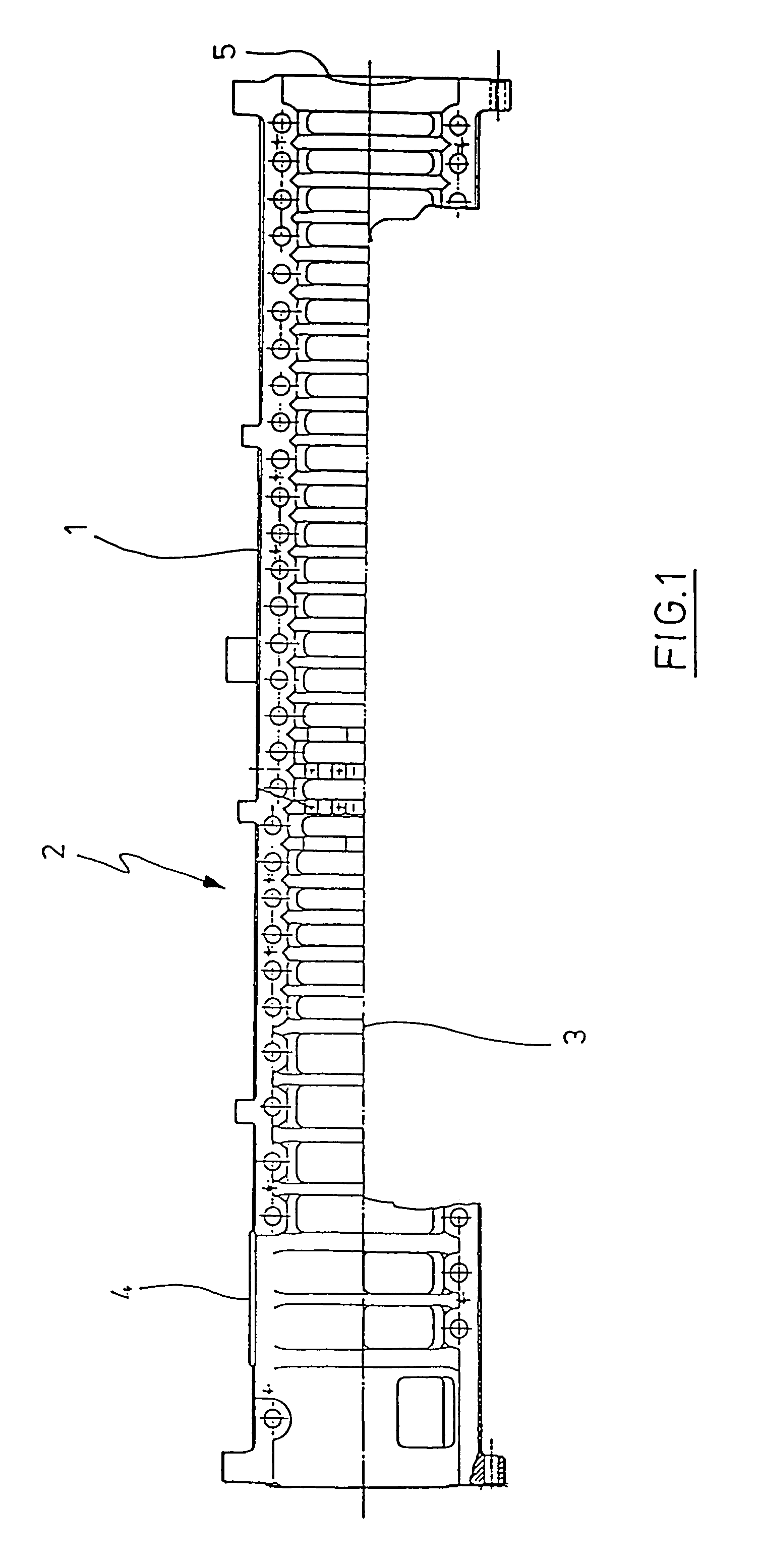
[0033]FIG. 1 shows a partially interrupted view of a framework (1) for cage bars of a pressing device (2) for expressing liquid substances from feed materials. The substances are conveyed along the longitudinal axis (3) of the drum from a material inlet (4) towards a dry substance outlet (5).

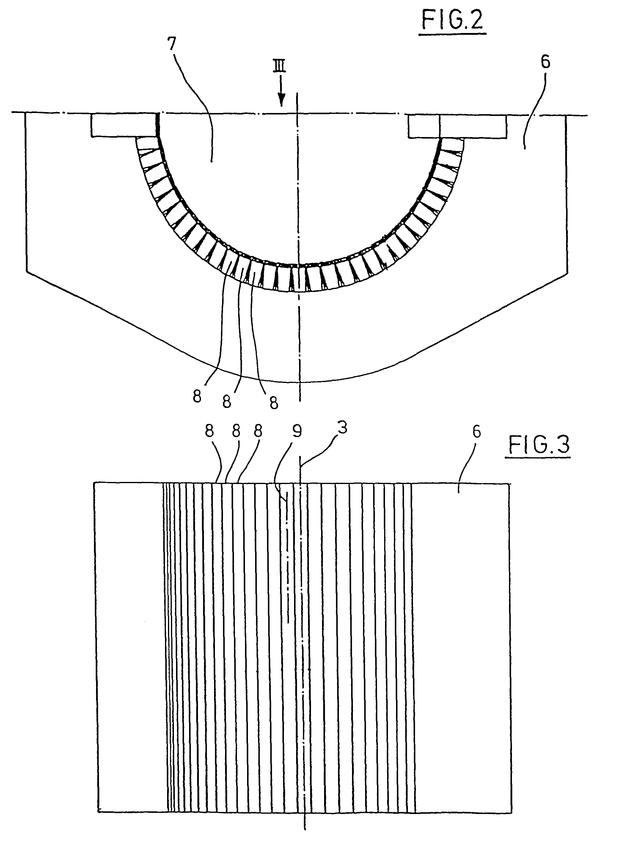
[0034]FIG. 2 shows a cross section through a drum half (6) of the pressing device (2). The drawing reveals that a plurality of cage bars (8) are arranged along a radial circumference of the drum interior (7).

[0035]The view in FIG. 3 shows that the longitudinal axes (9) of the cage bars (8) extend essentially parallel to the longitudinal axis (3) of the drum. Both FIG. 2 and FIG. 3 show that the cage bars (8) are very closely arranged relative to one another.

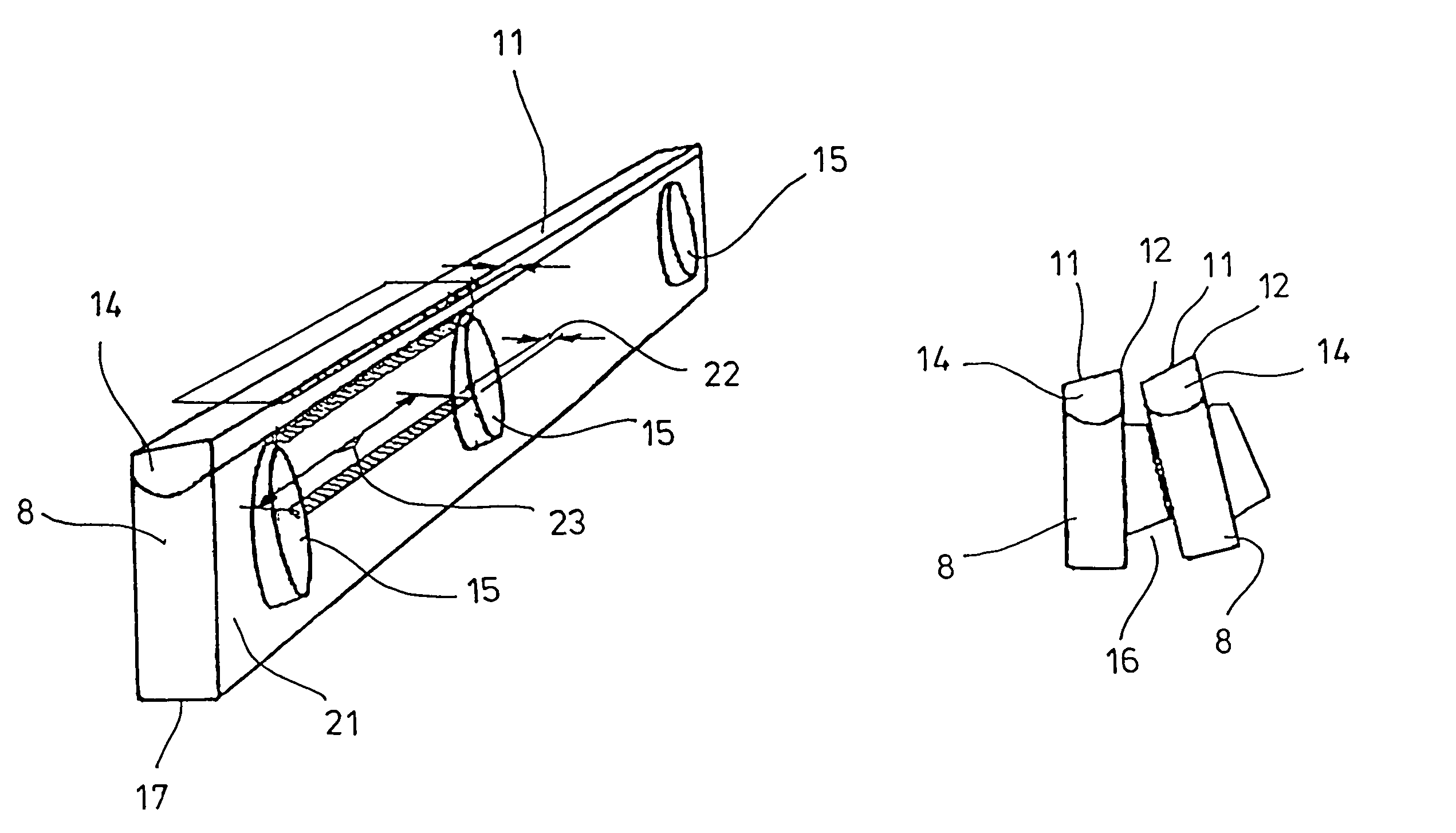
[0036]The design of the cage bars (8) is further illustrated by the enlarged view in FIG. 4. The drawing shows that each cage bar (8) consists of a body (10) and a wear surface (11). The wear surface (11) is bounded by a pressing edge (12). A...


PUM

PropertyMeasurementUnit
Thicknessaaaaaaaaaa
Shapeaaaaaaaaaa
Areaaaaaaaaaaa

Abstract

A press cage bar for a device for expressing liquids, which is bounded by at least one pressing edge in the area of a wear surface of a hard layer and which, in the area of at least one lateral face of the body of the cage bar, has at least one spacer that is raised above the lateral face. The spacer is formed as a deposit weld on the lateral face of the cage bar and is provided with a certain bottom clearance from the underside of the cage bar, which is on the opposite side of the cage bar from the wear surface. The spacer extends along the lateral face no farther than to the hard layer. The extent of the spacer transversely to a longitudinal axis of the lateral face is greater than its extent in the direction of the longitudinal axis of the lateral face. The spacer has increasing thickness perpendicular to the lateral face in a direction extending from the hard layer towards the underside of the cage bar.

Description

TITLE OF THE INVENTION[0001]The present application is a 371 of PCT / 01224 filed Jun. 14, 2004, which claims priority of German application 103 29 952.1 filed Jul. 3, 2003.BACKGROUND OF THE INVENTION[0002]The invention concerns a press cage bar for a device for expressing liquids, which is bounded by at least one pressing edge in the area of a wear surface of a hard layer and which, in the area of at least one lateral face of the body of the cage bar, has at least one spacer that is raised above the lateral face.[0003]The invention also concerns a device for expressing liquids, which has at least one press cage bar, which is bounded by at least one pressing edge in the area of a wear surface of a hard layer and which, in the area of at least one lateral face of the body of the cage bar, has at least one spacer that is raised above the lateral face.[0004]Press cage bars of the aforementioned type are used as devices for expressing liquids from materials placed in the device. It can be...

Claims


Application Information

Patent Timeline
IPC IPC(8): B30B9/26
CPCB30B9/26B30B9/267
Inventor VORREAU, LOTHARVOSS, GUNTER
Owner HARBURG FREUDENBERGER MASCHENBAU
Why Eureka
Try Eureka