Internal combustion engine and method for operating an internal combustion engine by means of a laser ignition unit

a laser ignition and internal combustion engine technology, applied in the direction of combustion types, combustion using lump and pulverulent fuel, electrical control, etc., can solve the problems of exhaust gases and reduce efficiency on the one hand, and achieve the effects of reliable ignition, improved exhaust emissions, and increased efficiency

Inactive Publication Date: 2010-08-03
ROBERT BOSCH GMBH
View PDF13 Cites 15 Cited by
  • Summary
  • Abstract
  • Description
  • Claims
  • Application Information

AI Technical Summary

Benefits of technology

[0008]The injection of the fuel is effected preferably by means of a multiplicity of individual streams, which are generated by means of a multi-port valve having preferably between seven and fourteen ports, or by means of an outward-opening annular gap valve (A valve) with an opening angle α of between 70°≦α≦110°.
[0009]Preferably, the period of time between the end of the fuel injection and the beginning of the ignition is selected such that it corresponds to a crankshaft angle travel of between 5° and 15°, in particular between 5° and 10°, and especially preferably 7.5°.
[0010]To enable faster and more reliable formation of the patty-shaped mixture region, a hollow, in which the patty-shaped mixture region forms, is preferably provided in the piston bottom. The hollow is preferably circular and symmetrical.
[0011]Especially preferably, ignition occurs near or at a middle region of the patty-shaped mixture region, so as to have the shortest possible flame travels through the entire mixture region.
[0012]Also preferably, a protruding nub over which the patty-shaped mixture region lies is formed on the piston bottom, so as to form a region that protrudes essentially in the axial direction of the piston in the patty-shaped mixture region. The ignition of the patty-shaped mixture region can preferably be effected beginning at the protruding region. As a result, it can be attained that the onset of the ignition of the patty-shaped mixture region takes place at an even earlier motion segment in the direction of top dead center of the piston, so that precisely in the optimal crankshaft angle range for efficiency, the most complete possible combustion of the patty-shaped mixture region takes place, and the expansion cycle then follows. To achieve positioning of the injection valve as centrally as possible in the cylinder head, the protruding nub is preferably disposed on a periphery of the hollow on the piston bottom. To achieve faster formation of the patty-shaped mixture region, a fuel injection is preferably effected at the nub that protrudes from the piston bottom.
[0013]Preferably, the fuel injection takes place in a plurality of successive intervals. As a result, a higher proportion of air is present in the patty-shaped mixture region, since between the individual intervals of the fuel injection, there is a small air cushion each time.
[0020]To reinforce the formation of the ignitable patty-shaped mixture region, the piston preferably has a substantially circular hollow on a piston bottom face. The hollow is preferably symmetrical to a center axis of the piston.
[0021]Also preferably, the piston has a protruding nub on the piston bottom face. The nub may preferably be provided in a circular hollow, or on the periphery of the hollow. By means of the protruding nub in the region of the hollow, it can be assured that the patty-shaped mixture region forms above the nub as well, so that one region of the mixture region protrudes in the direction of motion of the piston. The laser ignition device is then preferably disposed in such a way that the focal point of the laser is located in the protruding region of the mixture region. As a result, ignition long before top dead center of the piston can for instance be attained, yet the ignition still reliably takes place in the interior of the mixture region.

Problems solved by technology

In practice, however, in positioning the spark site of the spark plug, problems arise in positioning this spark site precisely in the narrow peripheral zone in the region of the ignitable fuel-air mixture.
These factors lead to reduced efficiency on the one hand and to problems with the exhaust gases on the other.

Method used


Image

  • Internal combustion engine and method for operating an internal combustion engine by means of a laser ignition unit
  • Internal combustion engine and method for operating an internal combustion engine by means of a laser ignition unit
  • Internal combustion engine and method for operating an internal combustion engine by means of a laser ignition unit

Examples


Embodiment Construction

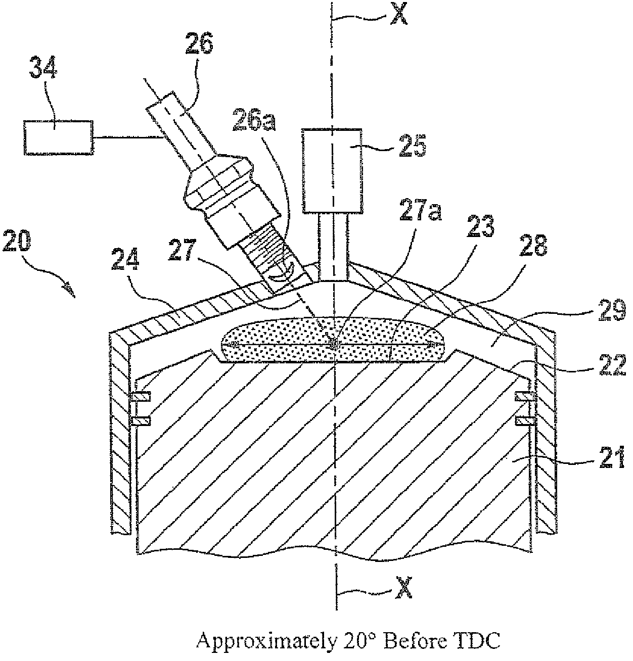
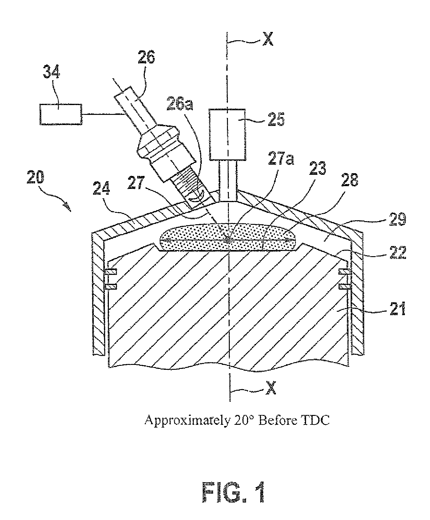
[0038]An internal combustion engine 20 in a first exemplary embodiment of the invention will now be described in conjunction with FIGS. 1 and 2.

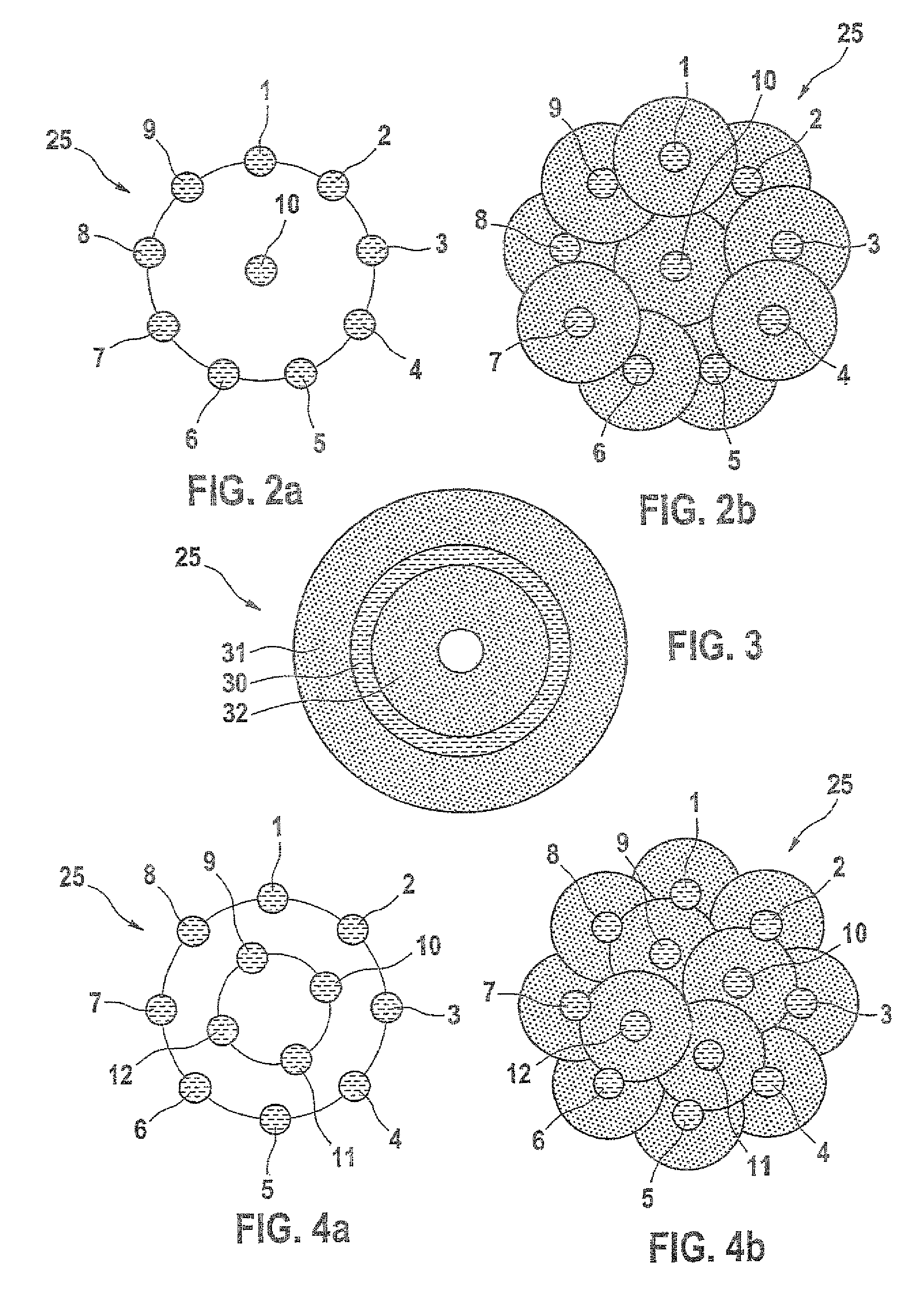
[0039]As shown in FIG. 1, the internal combustion engine 20 includes a piston 21, with a piston bottom 22 in which a circular hollow 23 is disposed centrally and symmetrically to a center axis X-X of the piston. The piston 21 moves in a cylinder in the known manner; an injection device 25 and a laser ignition device 26 are disposed in a cylinder head 24. The injection device 25 is disposed centrally in the cylinder head on the center axis X-X of the piston and in this exemplary embodiment, it is a multi-port valve with ten ports. The disposition of the ports can be seen in FIG. 2a. The laser ignition device 26 is controlled via a control unit 34 and has an aspherical lens 26a. The laser ignition device further includes a quality-switched optically pumped solid-state laser. The laser ignition device 26 generates a laser beam 27, which is aime...


PUM


Abstract

The invention relates to a method for operating an internal combustion engine including a fuel-injection unit and a laser ignition-unit. According to the invention, during a compression cycle of the internal combustion engine, fuel is injected into the combustion chamber by means of the fuel-injection unit in such a way that an ignitable, round, flat mixed region of fuel and air forms on a plunger and a predetermined period elapses between the end of the fuel injection and the start of ignition in order to form the round flat mixed region. Ignition then takes place within the flat round mixed region by means of the laser-ignition unit.

Description

CROSS-REFERNCE TO RELATED APPLICATION[0001]This application is a 35 USC 371 application of PCT / EP2006 / 066747 filed on Sep. 26, 2006BACKGROUND OF THE INVENTION[0002]1. Field of the Invention[0003]The present invention relates to an internal combustion engine having a laser ignition device for direct gasoline injection, and to a method for operating such an engine.[0004]2. Description of the Prior Art[0005]Internal combustion engines for direct gasoline injection are known in various designs from the prior art. Such engines are lately used more and more, since they have lower fuel consumption and low emissions. A common feature of the known engines is that they typically have an injection valve in a central position and a spark plug disposed in such a way that they are located on a periphery of the spray of fuel injected into the combustion chamber. The ignition of the fuel, which propagates essentially conically from the injection valve, is effected at the periphery of the cone, sinc...

Claims


Application Information

Patent Timeline
Patent Type & Authority Patents(United States)
IPC IPC(8): F02P23/04
CPCF02B23/105F02D41/3023F02P23/04F02B2023/102F02B2275/40F02D2041/389F02P5/152Y02T10/125F02P15/02Y02T10/12F02D41/30
Inventor VOGEL, MANFREDHERDEN, WERNERRIDDERBUSCH, HEIKO
Owner ROBERT BOSCH GMBH
Why Eureka
Try Eureka