Fuel injector having algorithm controlled look-ahead timing for injector-ignition operation

a fuel injector and algorithm control technology, applied in the direction of electric control, combustion air/fuel air treatment, instruments, etc., can solve the problems of injectors firing at room pressure, up to the practical compression limit of internal combustion engines, etc., to increase the fuel heating exposure time, reduce waste heat, and accelerate burn ignition

Inactive Publication Date: 2008-10-28
ECOMOTORS
View PDF23 Cites 46 Cited by
  • Summary
  • Abstract
  • Description
  • Claims
  • Application Information

AI Technical Summary

Benefits of technology

[0011]Likewise, each radical that is formed in the fuel injector utilizes chemical bond energy from the fuel such that the chemical bond energy in the main combustion chamber is reduced by that amount. It is therefore highly advantageous to minimize the number of free radicals formed to a level high enough to insure very high rate ignition, but low enough to minimize the degradation of the energy content of the injected fuel. In addition, most oxygen reduction catalysts also act as thermal cracking catalysts, particularly when heated to elevated temperatures in the 1,000° F. range and higher. Thermal cracking of the fuel in the injector is highly undesirable because it leads to carbon formation which initially fouls the catalytic surface and, if allowed to continue, actually impedes the flow of fuel through the injector. In addition, short chain cracked components typically have higher auto-ignition temperatures and higher heats of vaporization than octane and heptane, such that under commonly occurring laboratory conditions, excessively heating the injector will actually increase the ignition delay beyond the ideal situation as described above and also lead to rapid carbon formation.
[0013]In accordance with the principles of the invention, the required heat input to the fuel may be minimized by carefully controlling the external source of heating in conjunction with the fuel flow rate and fuel catalyst contact surface area, to produce an appropriate number of radicals without allowing the catalyzed oxidation process to significantly contribute thermal energy to the reaction zone. Such additional thermal energy would rapidly lead to thermal runaway and potentially consume all available oxygen, thereby significantly reducing the energy content of the resultant fuel and promoting carbon formation. This is of particular concern since commercial fuels may contain 1% to 10% oxygenator agents.
[0016]In accordance with the principles of the invention, preparation for a next engine firing starts immediately upon completion of a last engine firing wherein the fuel injector is substantially empty of fuel. The algorithm may adjust energy input into the fuel injector such that the fuel is heated to a selected temperature more rapidly at higher throttle settings than at lower throttle settings. Additionally, the algorithm allows up to four firing cycles of fuel to build up in the hot section to increase fuel heating exposure time during rapid acceleration. Waste heat is minimized by initiating a rapid burn ignition substantially at top dead center.

Problems solved by technology

In addition, the injector may fire at room pressure, and up to the practical compression limit of internal combustion engines.

Method used


Image

  • Fuel injector having algorithm controlled look-ahead timing for injector-ignition operation
  • Fuel injector having algorithm controlled look-ahead timing for injector-ignition operation
  • Fuel injector having algorithm controlled look-ahead timing for injector-ignition operation

Examples


Embodiment Construction

[0031]In the following paragraphs, the present invention will be described in detail by way of example with reference to the attached drawings. Throughout this description, the preferred embodiment and examples shown should be considered as exemplars, rather than as limitations on the present invention. As used herein, the “present invention” refers to any one of the embodiments of the invention described herein, and any equivalents. Furthermore, reference to various feature(s) of the “present invention” throughout this document does not mean that all claimed embodiments or methods must include the referenced feature(s).

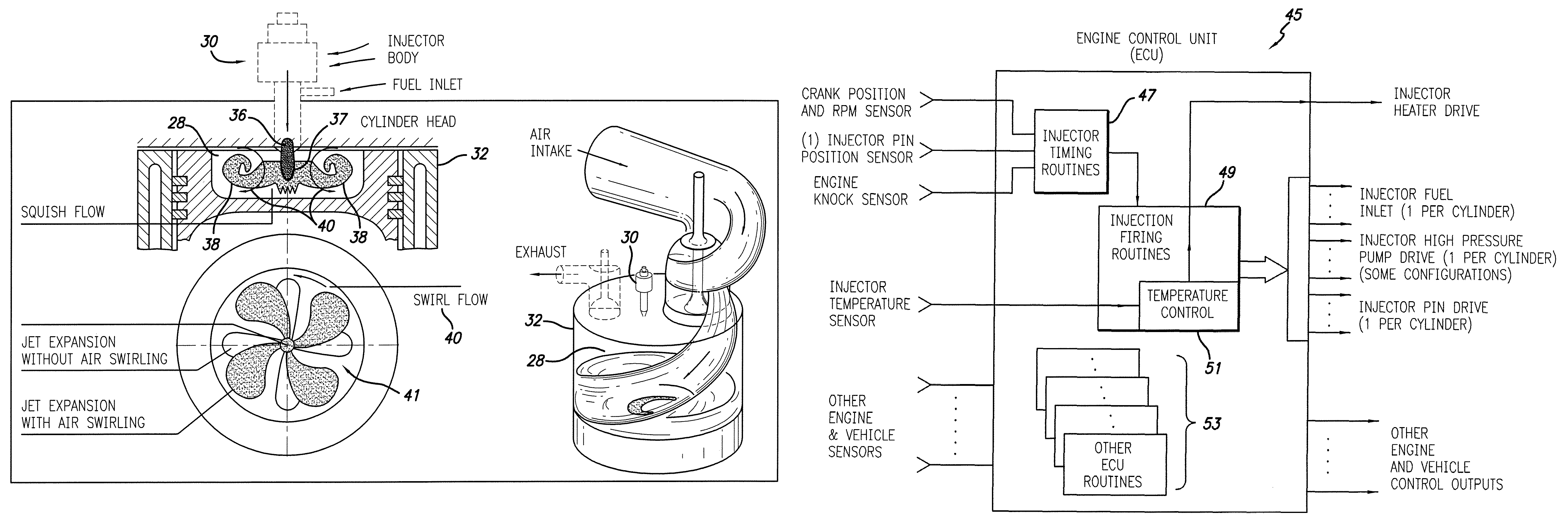
[0032]In accordance with the principles of the present invention, an injector-ignition fuel injection system for an internal combustion engine is provided, the system comprising an engine control unit (ECU) controlling a heated catalyzed fuel injector for heating and catalyzing a next fuel charge, wherein the ECU uses a one firing cycle look-ahead algorithm for contr...


PUM


Abstract

The present invention provides an injector-ignition fuel injection system for an internal combustion engine, comprising an ECU controlling a heated catalyzed fuel injector for heating and catalyzing a next fuel charge, wherein the ECU uses a one firing cycle look-ahead algorithm for controlling fuel injection. The ECU may further incorporate a look-up table, auto-tuning functions and heuristics to compensate for the rapid rotational de-acceleration that occurs near top dead center in lightweight small ultra-high compression engines as may be used with this invention. The ECU may further ramp heat input to the injector in response to engine acceleration requests and, under such circumstances, may extend its look-ahead for up to four firing cycles.

Description

REFERENCE TO RELATED APPLICATIONS[0001]This application claims the benefit of U.S. Provisional Patent Application No. 60 / 787,964, filed Mar. 31, 2006, the content of which is incorporated herein by reference in its entirety.FIELD OF THE INVENTION[0002]The invention broadly relates to fuel injection systems and more particularly to an injector-ignition fuel injector for an internal combustion engine having algorithm controlled timing for injector-ignition operation.BACKGROUND OF THE INVENTION[0003]Much of the world's energy consumption is dedicated to powering internal combustion based vehicles. Most gasoline and diesel car engines are only 20-30% efficient, such that a major portion of the hydrocarbon fuels is wasted, thereby depleting global resources while producing an excessive quantity of pollutants and greenhouse gasses. As illustrated in FIG. 1 (prior art), about one third of the energy used by a conventional engine manifests itself as waste heat in the cooling system (coolant...

Claims


Application Information

Patent Timeline
Patent Type & Authority Patents(United States)
IPC IPC(8): G06F19/00F02G5/00F02M51/00
CPCF02B31/00F02D41/0025F02M51/0671F02M53/06F02M57/00F02M69/047F02M27/02F02B3/06F02B23/0624F02B23/0669F02B2275/14Y02T10/16Y02T10/146Y02T10/123G06F16/583Y02T10/12
Inventor CHEIKY, MICHAEL C.
Owner ECOMOTORS
Why Eureka
Try Eureka