Endoscopic inflatable retraction device, method of using, and method of making

a technology retraction device, which is applied in the field of endoscopic inflatable retraction device, method of using, and making method, and can solve the problems of trauma to the retracted organ or tissue, delay the patient's recovery, and inconvenient us

Inactive Publication Date: 2010-08-03
COVIDIEN AG
View PDF98 Cites 14 Cited by
  • Summary
  • Abstract
  • Description
  • Claims
  • Application Information

AI Technical Summary

Benefits of technology

[0008]To provide the large surface area required to retract organs gently, the inflatable retraction device according to the invention is relatively large. As a result, the retraction device is normally juxtaposed between the entry through which surgical instruments pass into the body and the tissue to be treated. An inflatable retraction device according to the invention avoids obstructing the access of surgical instruments to the tissue to be treated by providing one or more apertures in the envelope of the device, such apertures allow instruments to pass into and out of the interior of the retraction device, or allow the tissue to be treated to enter the interior of the retraction device for treatment by instruments passed into the interior of the device. Treatment is thus carried out working through or inside the retraction device according to the invention.
[0010]According to different aspects of the invention, inflatable retraction devices according to the invention employ different ways to retain their ability to provide retraction while providing access for surgical instruments to the tissue to be treated or observed. An inflatable retraction device according to one aspect of the invention, such a retraction device being designated generally as a Type I retraction device, maintains its ability to provide retraction by means of an additional inflatable chamber, which forms a cage structure inside or outside the main inflatable chamber. The additional inflatable chamber is normally inflated after the main inflatable chamber of the retraction device has been inflated, and the retraction device has produced its desired retraction effect. Such an additional inflatable chamber is smaller and less powerful than the main inflatable chamber. Inflating the additional chamber alone would not always produce sufficient force to provide the desired retraction of the organ. However, the inflated additional chamber provides enough force to maintain an organ that has been retracted by the more powerful main inflatable chamber in its retracted position. The additional inflatable chamber is thus able to maintain the retraction effect of the retraction device after the retraction effect of the main inflatable chamber has been destroyed by piercing an aperture in the envelope of the main chamber to provide access to the tissue to be treated.
[0012]In an alternative embodiment of a retraction device according to the invention, the ability of the retraction device to provide a retraction effect during the treatment or observation procedure is maintained by keeping the main chamber of the retraction device in an inflated state during the treatment procedure. Such a retraction device, designated generally as a Type II retraction device, does not require an additional inflation chamber to maintain its retraction effect. An elastomeric window is attached to the inside of the retraction device after the device has been inflated. The elastomeric window provides a gas-tight seal around instruments passed through it, and around a tissue brought into the interior of the retraction device through it.
[0013]After the window has been installed, an instrument is passed through the window to pierce an aperture in the part of the envelope of the retraction device covered by the window to provide access to the organ to be treated. Surgical instruments are passed into the interior of the retraction device, primarily through the main inflation tube. The instruments can pass out of the retraction device to the tissue to be treated through the elastomeric window and the aperture in the envelope of the main chamber. Alternatively, the tissue to be treated enters the interior of the retraction device through the aperture and the elastomeric window. The elastomeric window provides a seal around the tissue to be treated enabling the retraction device to be maintained in its inflated state while treatment is carried out.
[0014]A Type I or a Type II retraction device according to the invention may be provided, according to a further aspect of the invention, with tabs attached to the interior surface of the envelope of the device. The tabs are gripped with a suitable gripping tool to adjust the position and orientation of the inflated retraction device relative to the tissue to be treated. The retraction device may be partially deflated to enable adjustments to be more easily made.

Problems solved by technology

Because such retractors have a relatively small surface area, they tend to damage and / or cause trauma to the retracted organs or tissue.
Moreover, the requirement for a plurality of incisions to heal may delay the patient's recovery.
Such a retractor reduces damage to retracted organs or tissues, but is inconvenient to use because it has to be kept in place by means of an external clamping arrangement, and its relatively large balloon tends to obstruct access to the site to be treated.

Method used


Image

  • Endoscopic inflatable retraction device, method of using, and method of making
  • Endoscopic inflatable retraction device, method of using, and method of making
  • Endoscopic inflatable retraction device, method of using, and method of making

Examples


Embodiment Construction

A. Inflatable Retraction Devices

[0078]1. Type IA Retraction Device—Basic Embodiment

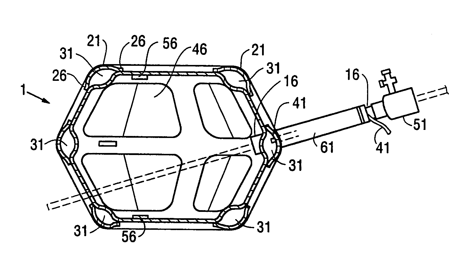
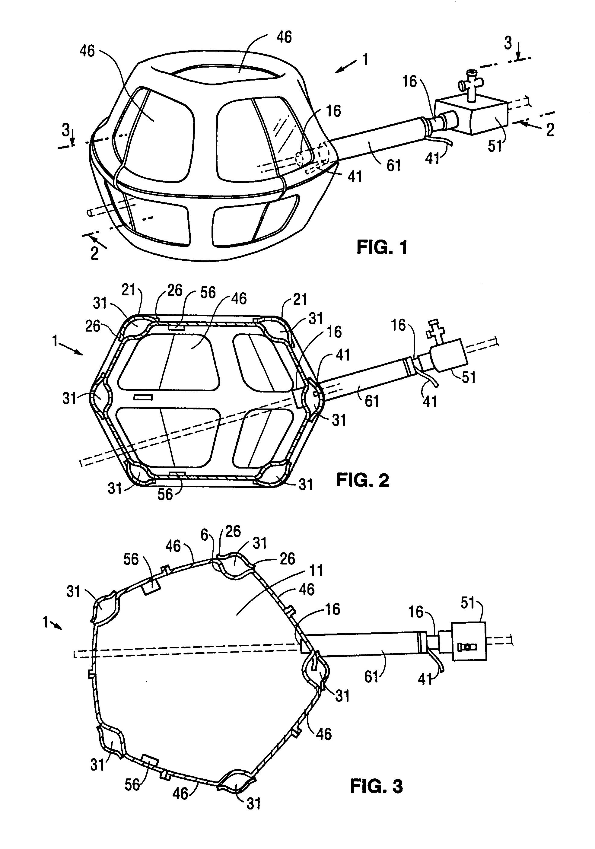
[0079]FIGS. 1, 2, and 3 show perspective, and vertical and horizontal cross sectional views, respectively, of a first embodiment 1 of a retraction device according to the invention. This type of retraction device has an additional inflatable chamber and will be designated as a Type I retraction device. The Type I retraction device shown in FIGS. 1, 2, and 3 with a segmented additional chamber will be designated a Type IA retraction device. The retraction device is shown in its inflated condition. The retraction device 1 comprises a main envelopes 6 enclosing a main inflatable chamber 11. The main envelope 6 is made of a relatively inelastic and tough film of a plastic such as Mylar®, polyethylene, or polyurethane. The preferred material for the main envelope 6 is a polyethylene and nylon composite. The thickness of the main envelope 6 is typically from 0.5 to 5 mils (13 to 130 microns). The proximal e...


PUM


Abstract

A method of providing access to tissue for a surgical instrument through a body wall is provided. The method includes providing an expandable retractor having a flexible sheath, the retractor being in a collapsed state; introducing the retractor into the body and placing the retractor adjacent the tissue; expanding the retractor; deploying the flexible sheath by engaging the flexible sheath with a tool and driving the flexible sheath through the body wall with the tool; and inserting the surgical instrument from outside the body through the flexible sheath to provide access to the tissue by the surgical instrument.

Description

[0001]This application is a Continuation of application Ser. No. 9 / 179,008, filed 26 Oct. 1998 (U.S. Pat. No. 6,605,037), which is a Continuation of application Ser. No. 8 / 561,160, filed 21 Nov. 1995 (U.S. Pat. No. 5,865,728), which is a Continuation-in-Part of application Ser. No. 8 / 106,231, filed 13 Aug. 1993 (now abandoned), which is a Divisional of Application Ser. No. 7 / 794,590, filed 19 Nov. 1991 (U.S. Pat. No. 5,309,896), which is a Continuation-in-Part of application Ser. No. 07 / 706,781, filed 29 May 1991 (now abandoned), of inventors Frederic H. Moll, Albert K. Chin, Diane E. Caramore, and Frank T. Watkins III.BACKGROUND OF THE INVENTION[0002]Laparoscopy dates back to the turn of the 20th Century. Early laparoscopic techniques were used primarily for diagnostic purposes to view the internal organs, without the necessity of conventional surgery. Since the 1930s, laparoscopy has been used for sterilization and, more recently, for the suturing of hernias. U.S. Pat. Nos. 4,919,...

Claims


Application Information

Patent Timeline
Patent Type & Authority Patents(United States)
IPC IPC(8): A61M29/00A61B17/00A61B17/02A61B17/22A61B17/32A61B17/34A61B19/00A61B19/02
CPCA61B17/0218A61B17/0281A61B17/22032A61B17/3417A61B19/26A61B17/3462A61B2017/00261A61B2017/00535A61B2017/00557A61B2017/320048A61B2017/3486A61B2019/5206A61B90/50A61B2090/306
Inventor MOLL, FREDERIC H.GRESL, JR., CHARLESCHIN, ALBERT K.HOPPER, PHILIP K.
Owner COVIDIEN AG
Why Eureka
Try Eureka