
Adjustable laser probe for use in vitreoretinal surgery

a laser probe and vitreoretinal technology, applied in the field of laser probes, can solve the problems of rigid cannulae, limited effectiveness of straight endoprobes, and inability to allow instruments

Active Publication Date: 2010-08-03
IRIDEX CORP
View PDF30 Cites 172 Cited by
  • Summary
  • Abstract
  • Description
  • Claims
  • Application Information

AI Technical Summary

Benefits of technology

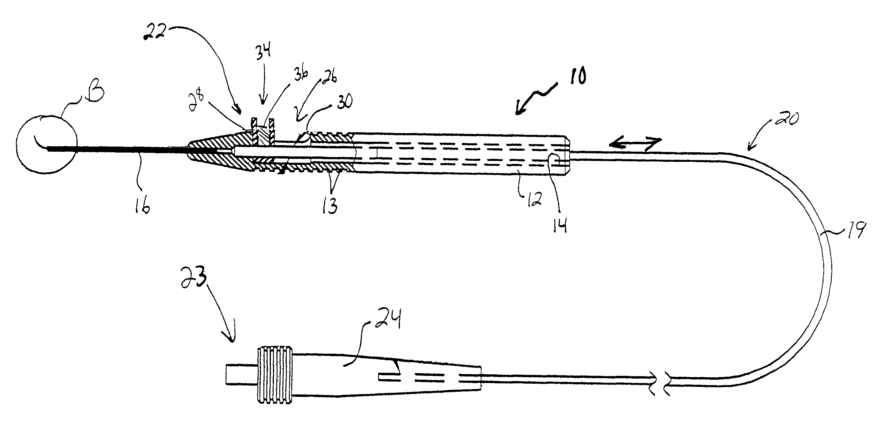
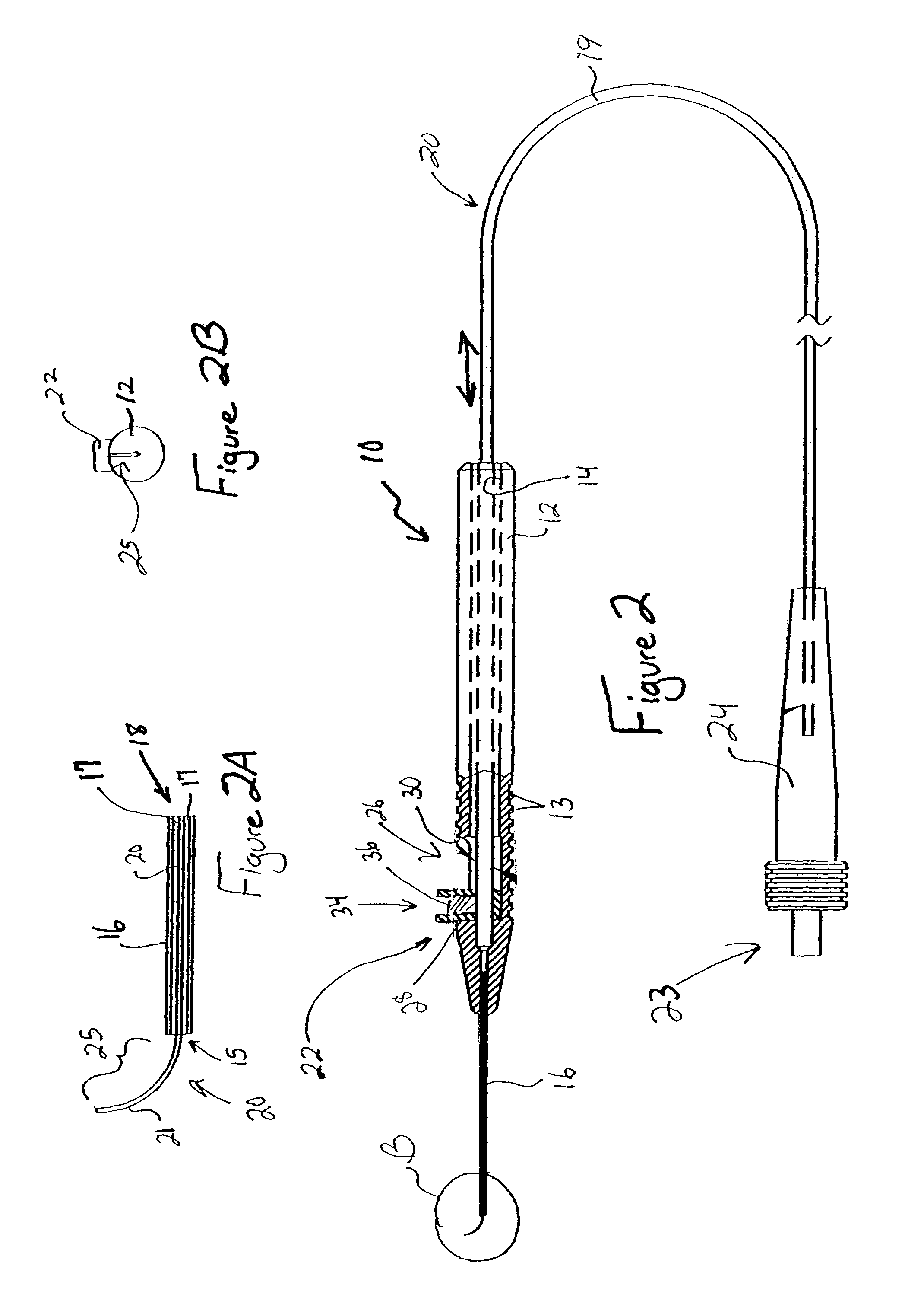
The present invention provides an eye laser probe that can be used as both a straight and a curved laser probe. The probe includes a handpiece and a rigid cannula fixed to the handpiece. The optical fiber for delivering laser energy extends through channels in the handpiece and cannula and is supported for translational movement therein. A slidable button is fixed to the optical fiber, via a rigid sleeve that supports the fiber such that the button and optical fiber move together in the same direction during operation. The button can be retracted relative to the handpiece to straighten the fiber or extended from the cannula to expose the fiber and allow it to curl into the curved tip configuration. The fiber can be selectively positioned relative to the button to cause the button to act as a visual indicator of the direction in which the fiber will extend from the cannula. The button is specially configured with an enlarged head portion to enhance grippability and smooth operation of the button.

Problems solved by technology

These cannulae are rigid and do not allow instruments with working ends larger than the diameter size to pass through.
However, a straight endoprobe's effectiveness is limited when the surgeon needs to apply laser energy to the peripheral areas of the retina.
This results in added cost to the patient and hospital, requires additional shelf space to store both types of probes, and results in more time to complete the vitrectomy.
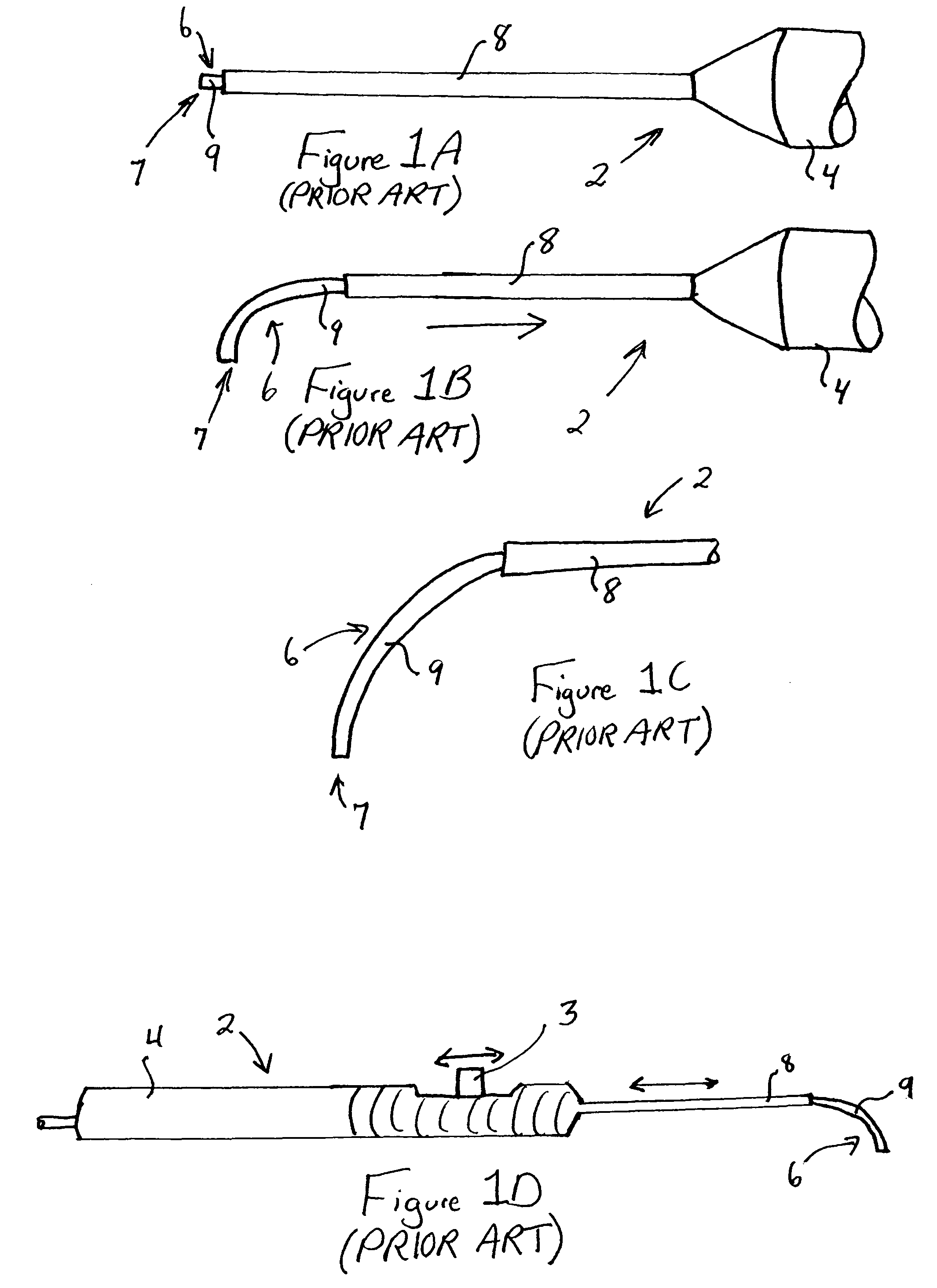
Additionally, the configuration of the probe is dangerous to a patient in that it operates in a manner that may result in damage to the patient's ocular tissue in unexpected circumstances, e.g. during quick withdrawal from the eye as when a patient “startles” under anesthesia.
Withdrawing the probe from the eye with the fiber in the curved tip configuration will cause ocular tissue to be damaged as the probe is withdrawn.
Accordingly, it is disadvantageous and dangerous to require advancement of the button 3 and sheath 8 (in a certain direction) at the time of withdrawal of the probe from the eye (in an opposite direction) in order to prevent damage to ocular tissue.

Method used


Image

  • Adjustable laser probe for use in vitreoretinal surgery
  • Adjustable laser probe for use in vitreoretinal surgery
  • Adjustable laser probe for use in vitreoretinal surgery

Examples


Embodiment Construction

[0025]The present invention provides a laser probe providing adjustability between straight and curved configurations that eliminates disadvantages associated with the prior art. This laser probe improves the surgeon's ability to reach critical areas within the eye, provides for safer and intuitive surgical maneuverability, and allows for quick visual inspection to confirm proper probe orientation, before extension of the fiber to expose a curved tip.

[0026]The endo ocular laser probe of the present invention can function as both a straight and a curved laser probe. Referring now to FIG. 2, the probe 10 generally includes an elongated handpiece 12 and a rigid cannula 16 fixed to the handpiece 12 to prevent relative translational movement therebetween. An optical fiber 20 for delivering laser energy extends through channels in the handpiece 12 and cannula 16 and is supported for translational movement therein. A slidable button 22 is fixed to the optical fiber 20, such that the button...


PUM


Abstract

A laser probe including a handpiece and a rigid cannula fixed to the handpiece to prevent relative translational movement-therebetween. An optical fiber for delivering laser energy is supported for translational movement relative to the handpiece. A slidable button is fixed to the optical fiber via a rigid sleeve such that the button and optical fiber move together in the same direction during operation. The fiber may be selectively positioned relative to the button to cause the button to act as a visual indicator of the direction in which the fiber will extend from the cannula. The button may be specially configured with an enlarged head portion to enhance grippability and smooth operation of the button.

Description

CROSS-REFERENCE TO RELATED APPLICATION[0001]This application claims the benefit of U.S. Provisional Patent Application No. 60 / 444,060, filed Jan. 31, 2003, the entire disclosure of which is hereby incorporated herein by reference.FIELD OF THE INVENTION[0002]The present invention relates generally to laser probes, and more particularly to an adjustable laser probe for effecting laser-induced photocoagulation to treat areas internal to the eye during vitreoretinal surgery.DISCUSSION OF RELATED ART[0003]A vitreoretinal specialist is an ophthalmic surgeon specializing in the diagnosis and treatment of the retina and vitreous. A vitreoretinal surgeon is often called upon to perform a vitrectomy procedure, which typically involves making three stab incisions for access to the posterior segment (back part) of the eye, i.e. the vitreous cavity. One of those incisions (inferio-temporally) is ultimately used for insertion of an infusion cannula, which is used during surgery to introduce fluid...

Claims


Application Information

Patent Timeline
Patent Type & Authority Patents(United States)
IPC IPC(8): A61B18/18A61B17/00A61B18/00A61B18/22A61F9/008
CPCA61F9/008A61F9/00821A61B18/22A61B2017/00424A61B2018/00196A61F2009/00874
Inventor MC GOWAN, SR., MICHAEL J.HURST, JR., CHARLES R.LAMBERT, HARRY MICHAELLUMPKIN, CHRISTOPHER F.
Owner IRIDEX CORP
Learn More