
Method and apparatus for improved burst mode during power conversion

a burst mode and power conversion technology, applied in the field of power conversion, can solve the problems of rapid depletion of fossil energy reserves currently being used to generate electricity, inconvenient use, and inability to meet the needs of the user,

Active Publication Date: 2010-08-03
ENPHASE ENERGY
View PDF21 Cites 95 Cited by
  • Summary
  • Abstract
  • Description
  • Claims
  • Application Information

AI Technical Summary

Benefits of technology

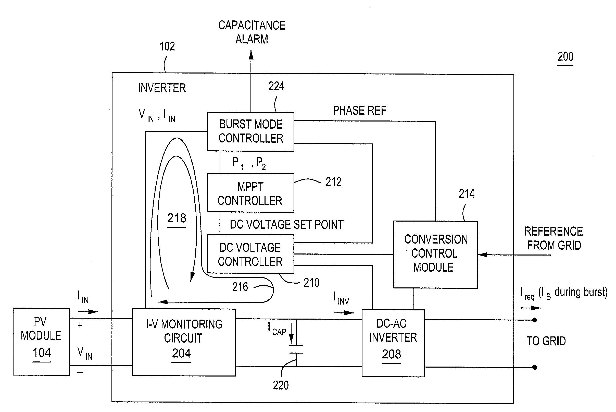
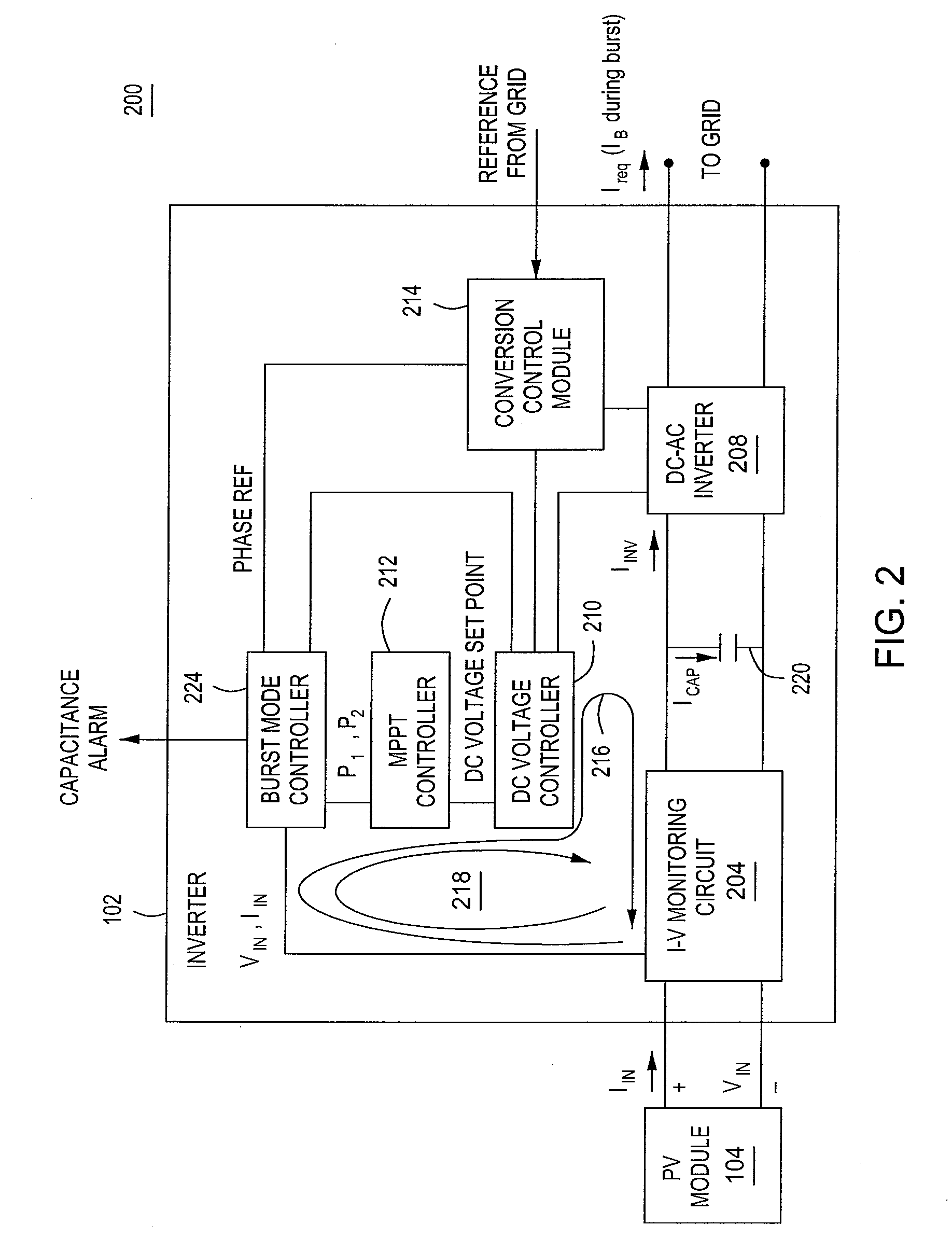
The present invention is about a method and apparatus for converting DC input power to AC output power. The apparatus includes an input capacitor, a DC-AC inverter, a burst mode controller, a first feedback loop, and a second feedback loop. The burst mode controller causes energy to be stored in the input capacitor during at least one storage period and the energy to be drawn from the input capacitor during at least one burst period, wherein the AC output power is greater than the DC input power during the at least one burst period. The first feedback loop determines a maximum power point (MPP) and operates the DC-AC inverter proximate the MPP. The second feedback loop determines a difference in a first power measurement and a second power measurement, produces an error signal indicative of the difference, and couples the error signal to the first feedback loop to adjust at least one operating parameter of the DC-AC inverter to drive toward the MPP. The technical effect of this invention is to provide a more efficient and reliable method and apparatus for converting DC input power to AC output power.

Problems solved by technology

Due to the high cost of installation, solar panels were not an economical choice for generating power unless no other power options were available.
However, the worldwide growth of energy demand is leading to a durable increase in energy cost.
In addition, it is now well established that the fossil energy reserves currently being used to generate electricity are rapidly being depleted.
During the time period required for an MPPT technique to bias a PV module to its MPP, for example, when the solar irradiance on a PV module changes from no irradiance to increasing irradiance or at a PV module / inverter initial activation, a power conversion device coupled to the PV module will suffer from a lower efficiency until the MPP is achieved.
Additionally, a power conversion device coupled to a PV module generally will suffer from a lower efficiency when the PV module is operating at a low power, e.g., low irradiance.
During low irradiance, a PV module and an associated inverter may operate so inefficiently that is it best for overall system efficiency to deactivate the PV module and / or its inverter until solar irradiance increases.

Method used


Image

  • Method and apparatus for improved burst mode during power conversion
  • Method and apparatus for improved burst mode during power conversion
  • Method and apparatus for improved burst mode during power conversion

Examples


Embodiment Construction

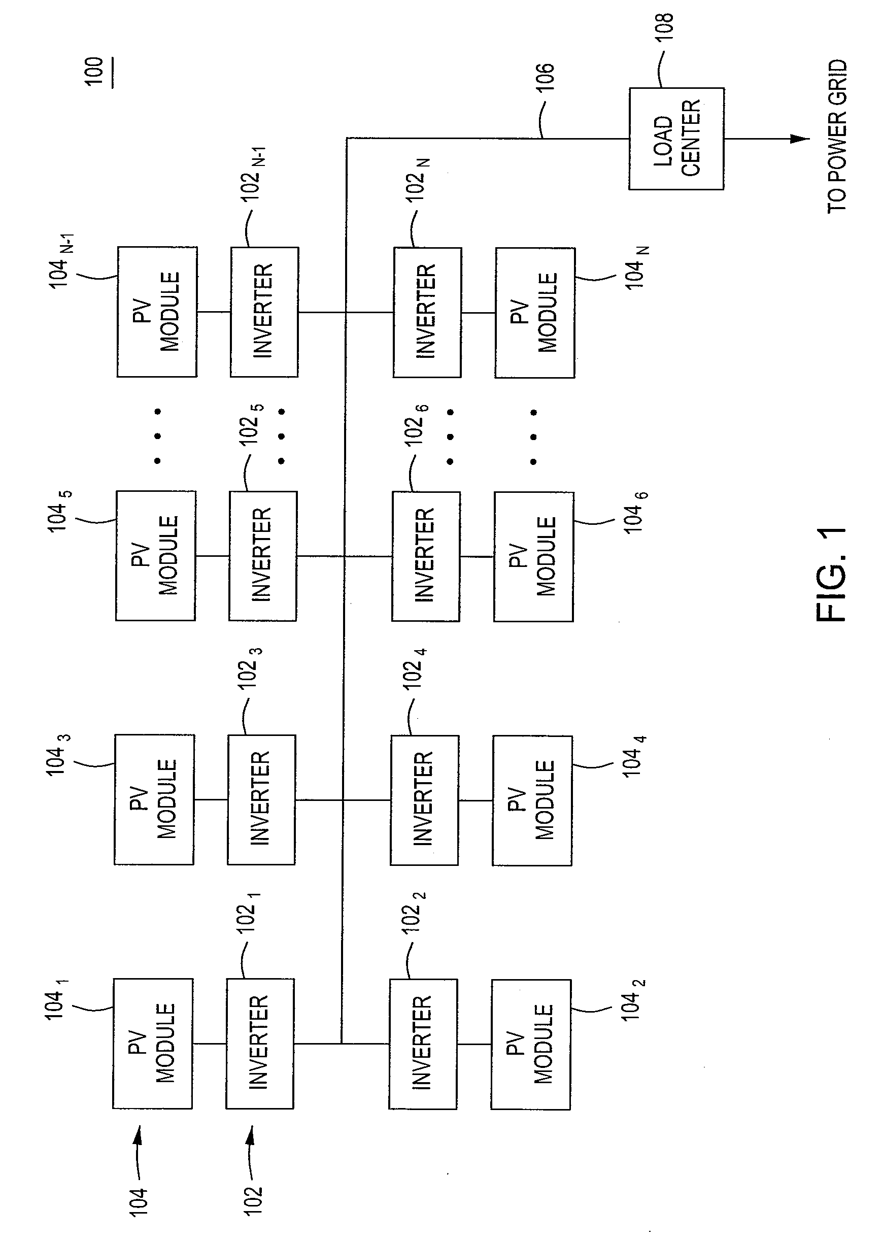
[0018]FIG. 1 is a block diagram of a system 100 for distributed generation (DG) in accordance with one or more embodiments of the present invention. This diagram only portrays one variation of the myriad of possible system configurations. The present invention can function in a variety of distributed power generation environments and systems.

[0019]The system 100 comprises a plurality of inverters 1021, 1022 . . . 102n, collectively referred to as inverters 102, a plurality of PV modules 1041, 1042 . . . 104n, collectively referred to as PV modules 104, an AC bus 106, and a load center 108.

[0020]Each inverter 1021, 1022 . . . 102n is coupled to a PV module 1041, 1042 . . . 104n, respectively. In some embodiments, a DC-DC converter may be coupled between each PV module 104 and each inverter 102 (e.g., one converter per PV module 104). Alternatively, multiple PV modules 104 may be coupled to a single inverter 102 (i.e., a centralized inverter); in some embodiments, a DC-DC converter ma...


PUM


Abstract

A method and apparatus for converting DC input power to AC output power. The apparatus comprises an input capacitor, a DC-AC inverter, a burst mode controller for causing energy to be stored in the input capacitor during at least one storage period and the energy to be drawn from the input capacitor during at least one burst period, wherein the AC output power is greater than the DC input power during the at least one burst period; a first feedback loop for determining a maximum power point (MPP) and operating the DC-AC inverter proximate the MPP; and a second feedback loop for determining a difference in a first power measurement and a second power measurement, producing an error signal indicative of the difference, and coupling the error signal to the first feedback loop to adjust at least one operating parameter of the DC-AC inverter to drive toward the MPP.

Description

BACKGROUND OF THE INVENTION[0001]1. Field of the Invention[0002]Embodiments of the present disclosure generally relate to power conversion and, more particularly, to a method and apparatus for improved burst mode operation.[0003]2. Description of the Related Art[0004]Solar panels have historically been deployed in mostly remote applications, such as remote cabins in the wilderness or satellites, where commercial power was not available. Due to the high cost of installation, solar panels were not an economical choice for generating power unless no other power options were available. However, the worldwide growth of energy demand is leading to a durable increase in energy cost. In addition, it is now well established that the fossil energy reserves currently being used to generate electricity are rapidly being depleted. These growing impediments to conventional commercial power generation make solar panels a more attractive option to pursue.[0005]Solar panels, or photovoltaic (PV) mod...

Claims


Application Information

Patent Timeline
Patent Type & Authority Patents(United States)
IPC IPC(8): H01H9/54
CPCG05F1/67H02J3/385H02M7/42Y02E10/58H02J2300/26H02J3/381Y02E10/56H02J7/35H02M7/48
Inventor FORNAGE, MARTIN
Owner ENPHASE ENERGY
Learn More