Dynamically adaptive method for determining the state of charge of a battery

a battery and dynamic adaptive technology, applied in the field of batteries, can solve the problems of reducing the utility of the prior art system and the impracticality of coulomb counting

Inactive Publication Date: 2010-08-03
GM GLOBAL TECH OPERATIONS LLC
View PDF11 Cites 60 Cited by
  • Summary
  • Abstract
  • Description
  • Claims
  • Application Information

AI Technical Summary

Problems solved by technology

A difficulty with the prior art approaches is that they are either not vehicle specific, or lack a generalized approach to multiple parameter handling, thereby reducing the utility of the prior art systems.
Because this is not normally the case, Coulomb counting tends to be an impractical solution.

Method used


Image

  • Dynamically adaptive method for determining the state of charge of a battery
  • Dynamically adaptive method for determining the state of charge of a battery
  • Dynamically adaptive method for determining the state of charge of a battery

Examples


Embodiment Construction

[0018]The following detailed description is merely exemplary in nature and is not intended to limit the invention or the application and uses of the invention. Furthermore, there is no intention to be bound by any expressed or implied theory presented in the preceding technical field, background, brief summary or the following detailed description.

[0019]Techniques and technologies may be described herein in terms of functional and / or logical block components and various processing steps. It should be appreciated that such block components may be realized by any number of hardware, software, and / or firmware components configured to perform the specified functions. For example, an embodiment of a system or a component may employ various integrated circuit components, e.g., memory elements, digital signal processing elements, logic elements, look-up tables, or the like, which may carry out a variety of functions under the control of one or more microprocessors or other control devices....


PUM


Abstract

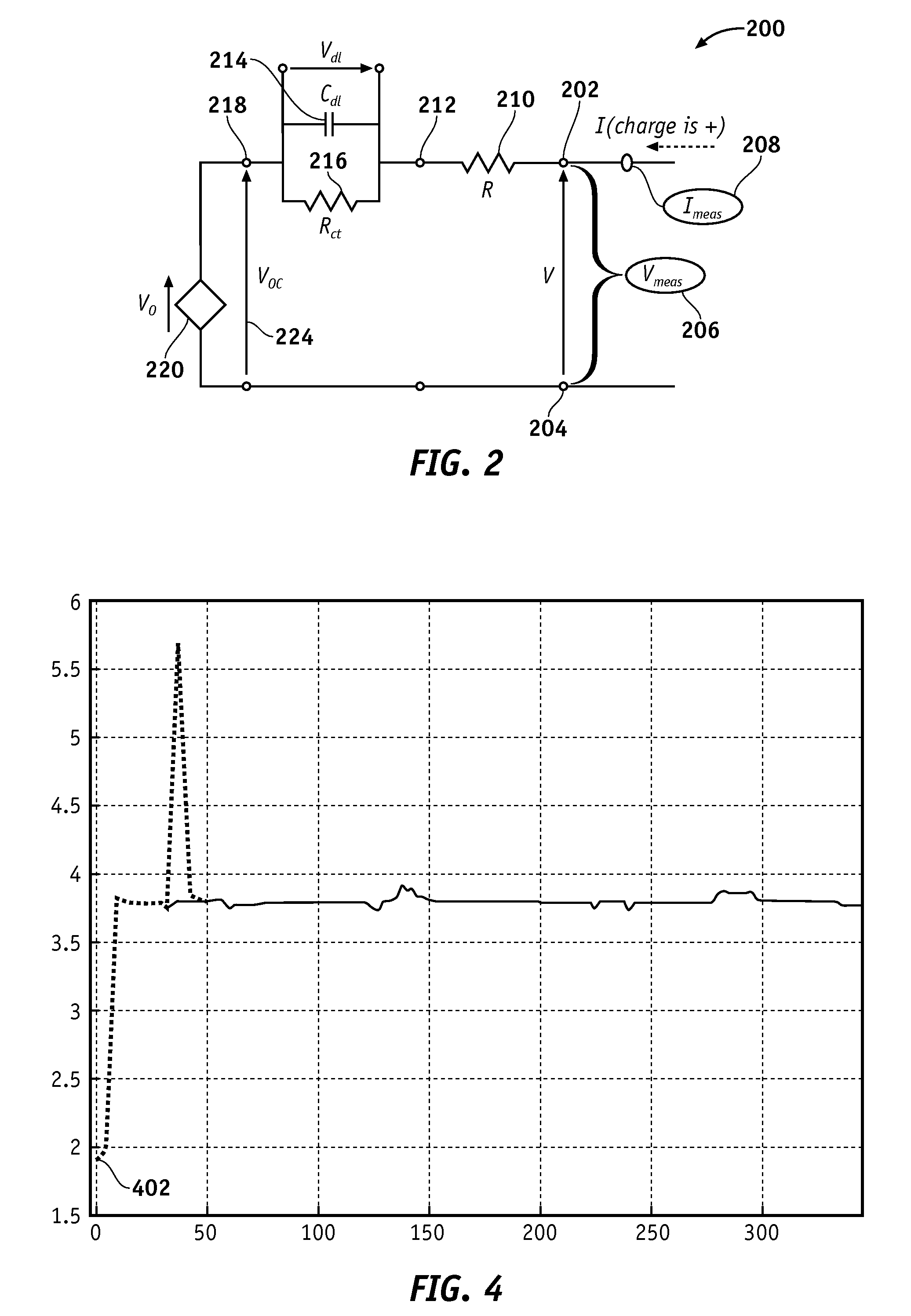
A method for determining the state of charge (SOC) of a lithium ion battery is provided. The method leverages a circuit model of the lithium ion battery, and generates four battery parameters from which the SOC is derived.

Description

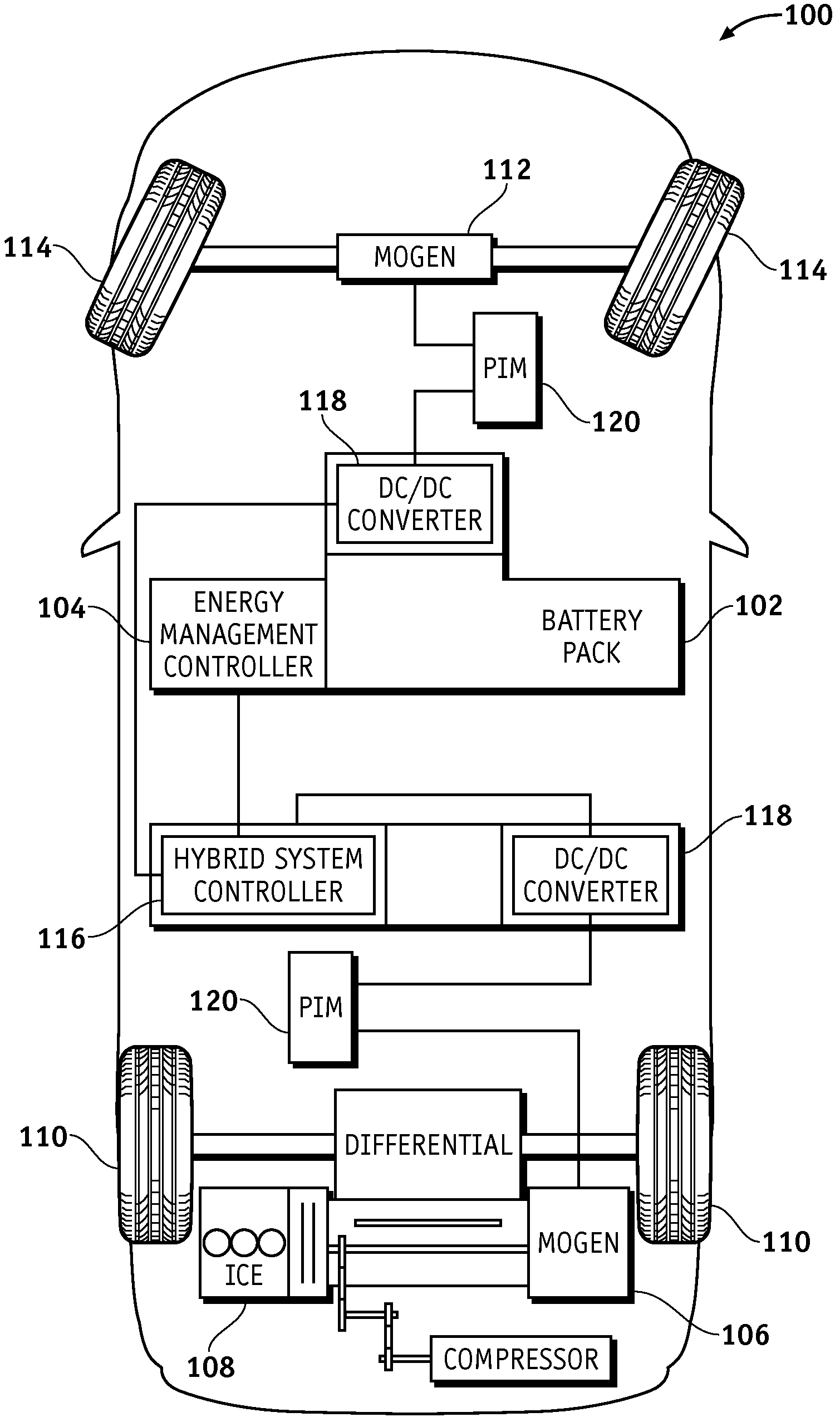
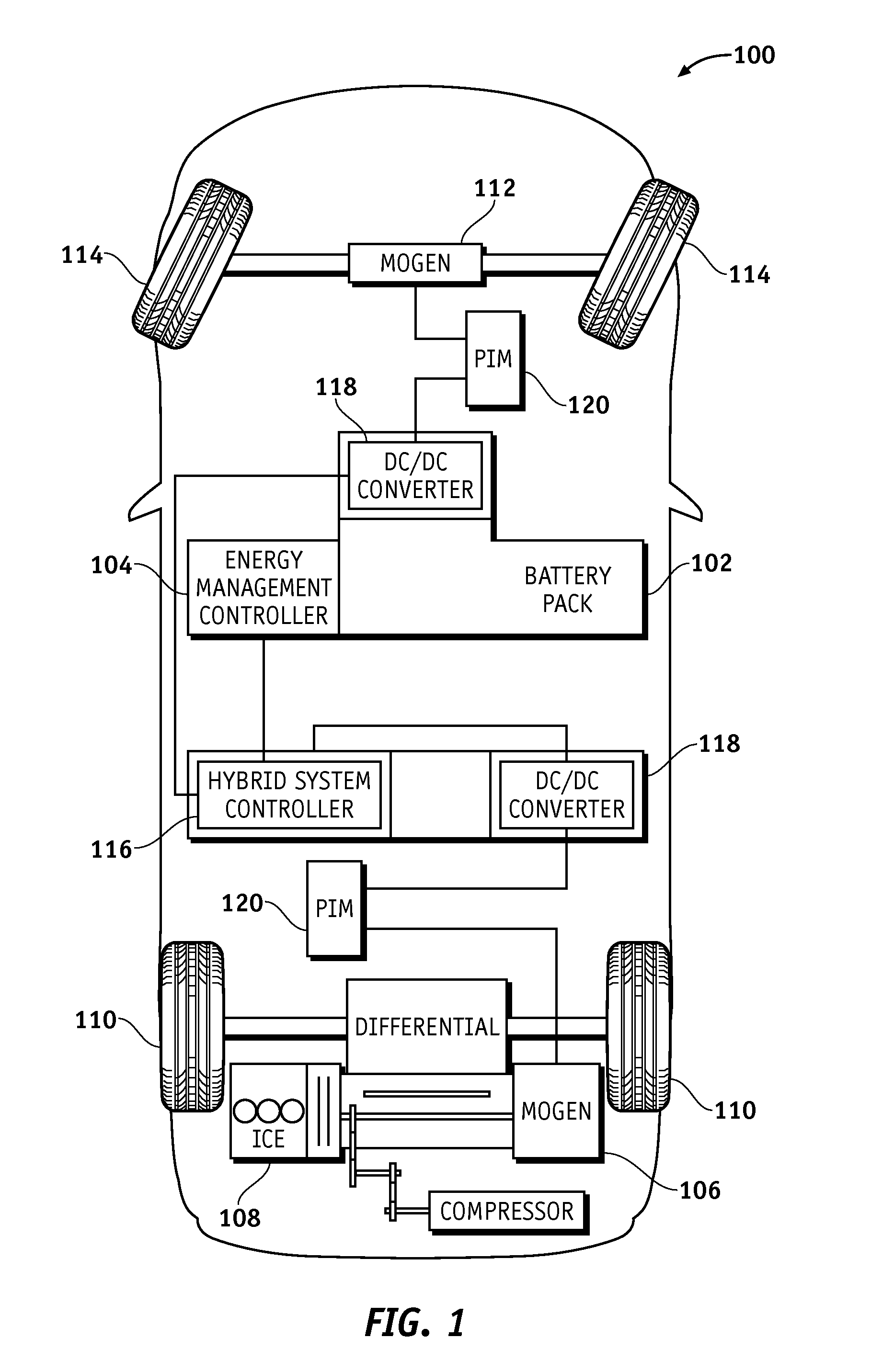
TECHNICAL FIELD[0001]The subject matter described herein generally relates to batteries used for electric or hybrid electric drivetrains, and more particularly relates to a method for recursively determining a state of charge in a battery system.BACKGROUND[0002]In today's automotive market, there exist a variety of propulsion or drive technologies used to power vehicles. The technologies include internal combustion engines (ICEs), electric drive systems utilizing batteries and / or fuel cells as an energy or power source, hybrid systems utilizing a combination of internal combustion engines and electric drive systems, and pure electric systems. The propulsion systems each have specific technological, financial, and performance advantages and disadvantages, depending on the state of energy prices, energy infrastructure developments, environmental laws, and government incentives.[0003]The increasing demand to improve fuel economy and reduce emissions in present vehicles has led to the d...

Claims


Application Information

Patent Timeline
Patent Type & Authority Patents(United States)
IPC IPC(8): H02J7/00
CPCH01M10/441H01M10/443H01M10/482H01M10/0525Y02T10/7011H01M10/448H01M10/446G01R31/367Y02E60/10
Inventor LIN, JIANTANG, XIDONGKOCH, BRIAN J.FRISCH, DAMON R.GIELNIAK, MICHAEL J.
Owner GM GLOBAL TECH OPERATIONS LLC
Why Eureka
Try Eureka