
Application based active-active data center network using route health injection and IGP

a data center network and active-active technology, applied in the field of data center topology, can solve the problems of centralized data centers rarely being able to provide the necessary reliability, service is susceptible to interruption, performance severely affected,

Inactive Publication Date: 2010-08-03
CISCO TECH INC
View PDF34 Cites 42 Cited by
  • Summary
  • Abstract
  • Description
  • Claims
  • Application Information

AI Technical Summary

Benefits of technology

The present invention relates to a data center topology that can recover from a disaster and provide load balancing for applications between two data centers. The invention uses route health injection and Border Gateway Protocol to optimize business continuance, disaster recovery, and load balancing. The invention also includes an active / active data center design that allows for quick recovery from a disaster at one of the data centers. The technical effects of the invention include improved reliability, reduced costs, and improved performance and load balancing for critical applications.

Problems solved by technology

Unfortunately, centralized data centers are rarely capable of providing the necessary reliability required under common service level agreements for a geographically diverse organization and the service is susceptible to interruption in the event of a disaster, such as a fire or earthquake, equipment malfunction or denial of service attack.
Unfortunately, when DNS is utilized to direct traffic to the appropriate data center, performance is severely affected when one data center experiences a loss of a server or other disaster because the time it takes to clear the DNS cache throughout the network can take over 20 minutes and in certain cases more than 24 hours.
During this time, traffic cannot be re-routed to the other data center.
In other instances, application http-redirection is used to perform these tasks but even worse delays are experienced when there is a disaster at one of the data centers.
Clearly, this extensive delay is unacceptable.

Method used


Image

  • Application based active-active data center network using route health injection and IGP
  • Application based active-active data center network using route health injection and IGP
  • Application based active-active data center network using route health injection and IGP

Examples


Embodiment Construction

[0012]In the description herein for embodiments of the present invention, numerous specific details are provided, such as examples of components and / or methods, to provide a thorough understanding of embodiments of the present invention. One skilled in the relevant art will recognize, however, that an embodiment of the invention can be practiced without one or more of the specific details, or with other apparatus, systems, assemblies, methods, components, materials, parts, and / or the like. In other instances, well-known structures, materials, or operations are not specifically shown or described in detail to avoid obscuring aspects of embodiments of the present invention.

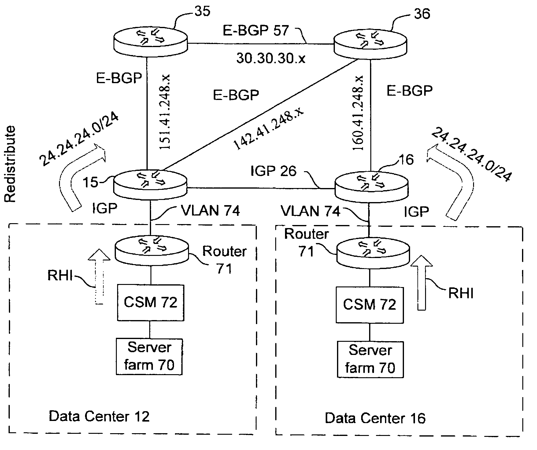
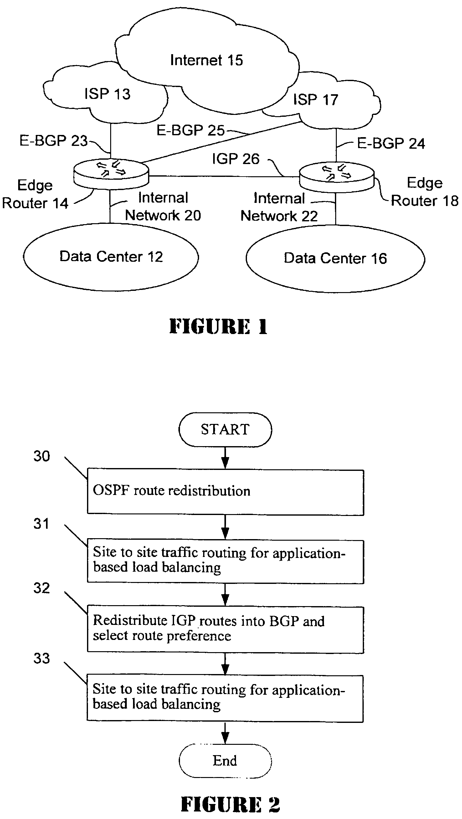
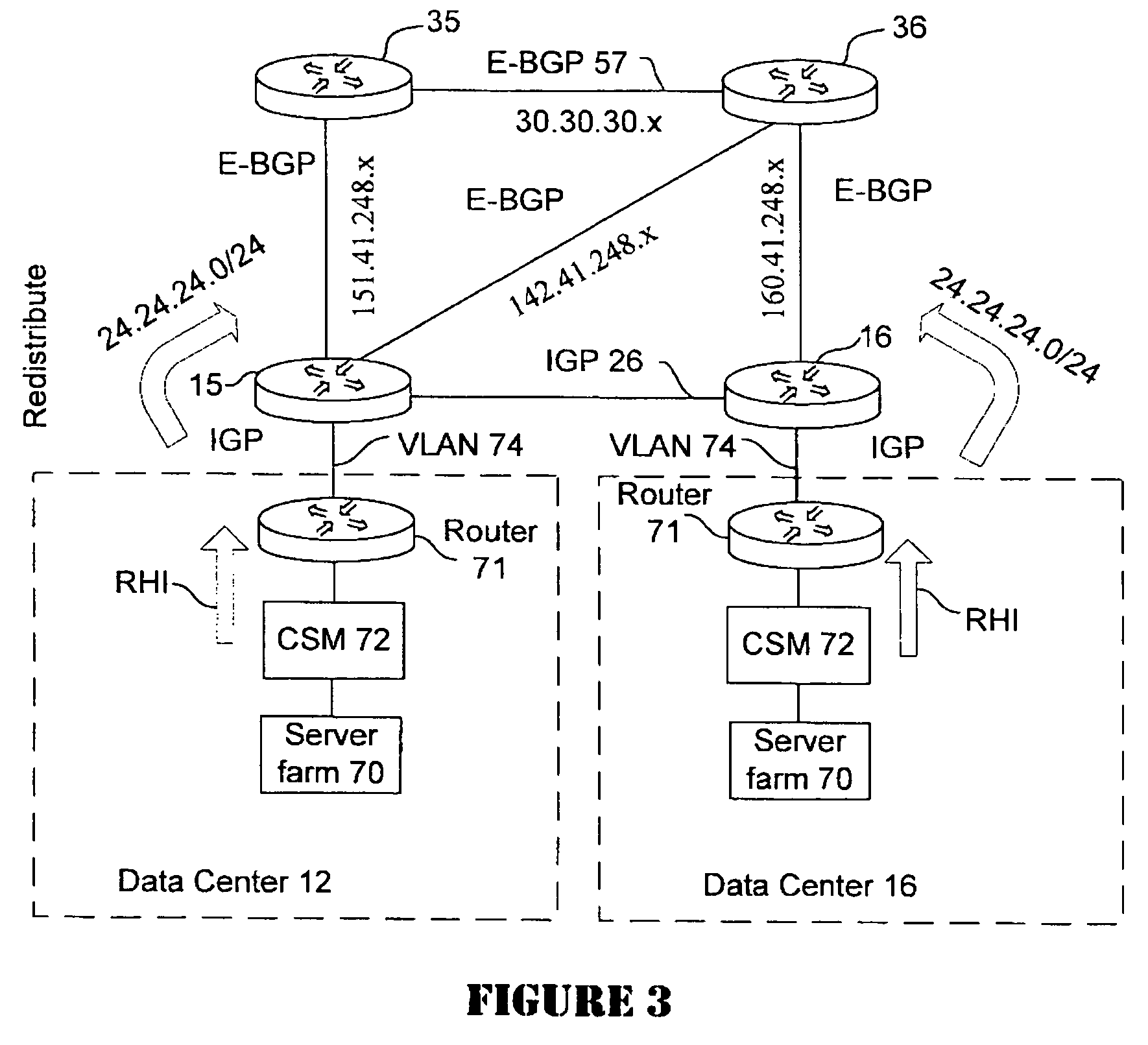
[0013]Referring now to the drawings more particularly by reference numbers, a simplified block diagram of a representative active / active data center is shown in FIG. 1. Data center 12 interfaces to two internet service providers (ISP) 13 and 17 through edge router 14. ISPs 13 and 17 are part of the world wide web an...


PUM


Abstract

A distributed data center topology having at least a pair of active data centers that can recover from a disaster at one of the data centers and achieves load balancing using IGP (Interior Gateway Protocol) between data centers. The distributed data centers use virtual IP addresses, route health injection and Border Gateway Protocol (BGP) for business continuance, disaster recovery and load balancing. Active applications are deployed at each data center to provide a logical active / standby configuration for certain applications. Alternatively, active applications are deployed at both sites and BGP routes traffic to the closest data center edge router. Load balancing occurs over an internal IGP link between sites.

Description

COPYRIGHT NOTICE[0001]A portion of the disclosure recited in the specification contains material that is subject to copyright protection. Specifically, documents provided with this application include source code instructions for a process by which the present invention is practiced in a computer system. The copyright owner has no objection to the facsimile reproduction of the specification as filed in the Patent and Trademark Office. Otherwise, all copyright rights are reserved.RELATED APPLICATIONS[0002]This application is related to the following and commonly-assigned U.S. patent applications Ser. No. 11 / 065,871, entitled Disaster Recovery For Active-Standby Data Center Using Route Health And BGP and Ser. No. 11 / 067,037, entitled Active-Active Data Center Using RHI, BGP, And IP Anycast For Disaster Recovery And Load Distribution, both of which were filed on Feb. 25, 2005 by Zeeshan Naseh and Vinay Gundi, the disclosures of which are incorporated herein by reference for all purpose...

Claims


Application Information

Patent Timeline
Patent Type & Authority Patents(United States)
IPC IPC(8): G06F15/173
CPCH04L45/00H04L67/1008H04L67/1006H04L67/1002H04L67/1001
Inventor NASEH, ZEESHANGUNDI, VINAY
Owner CISCO TECH INC
Learn More