
Method for producing triangular elements designed for the manufacture of structures and resulting triangular elements

a triangular element and manufacturing method technology, applied in the field of manufacturing process for executing plane, curvilinear, polyhedral and spherical structures, can solve the problems of preventing the proceeding of using monobloc triangular structures, preventing the proceeding of using assembled triangular structures, etc., to increase the insulation of the inner space of the structur

Inactive Publication Date: 2010-08-10
NEFZI ABDESSATAR
View PDF43 Cites 9 Cited by
  • Summary
  • Abstract
  • Description
  • Claims
  • Application Information

AI Technical Summary

Benefits of technology

"The present invention provides a process for manufacturing triangular structures with improved characteristics. These triangles are made up of a series of monobloc triangles that are assembled and then fixed to a final structure using a mold. The triangles have certain features, such as angled outer surfaces, inner shouldering, and grooves for seal members. The process allows for the manufacturing of triangles with these features and ensures a watertight seal with adjacent structures. The triangles can also be coated with covering surfaces to form a double wall. The process includes shaping the triangles, assembling them, and using a mold to create the final structure. The triangles can also have hollowing-outs for fluid circulation and insulation. Overall, the process improves the manufacturing of triangles with better characteristics."

Problems solved by technology

Nevertheless, nothing prevents from proceeding by using monobloc triangular structures, as for domes, in order to construct green-houses with chapel shape.
For such tourist use, which means for pressure levels not exceeding three (3) absolute atmospheres, nothing, however, prevents from proceeding by using assembled triangular structures, as for domes, since such assembling ensures water tightness for the final structure of the bell.

Method used


Image

  • Method for producing triangular elements designed for the manufacture of structures and resulting triangular elements
  • Method for producing triangular elements designed for the manufacture of structures and resulting triangular elements
  • Method for producing triangular elements designed for the manufacture of structures and resulting triangular elements

Examples


Embodiment Construction

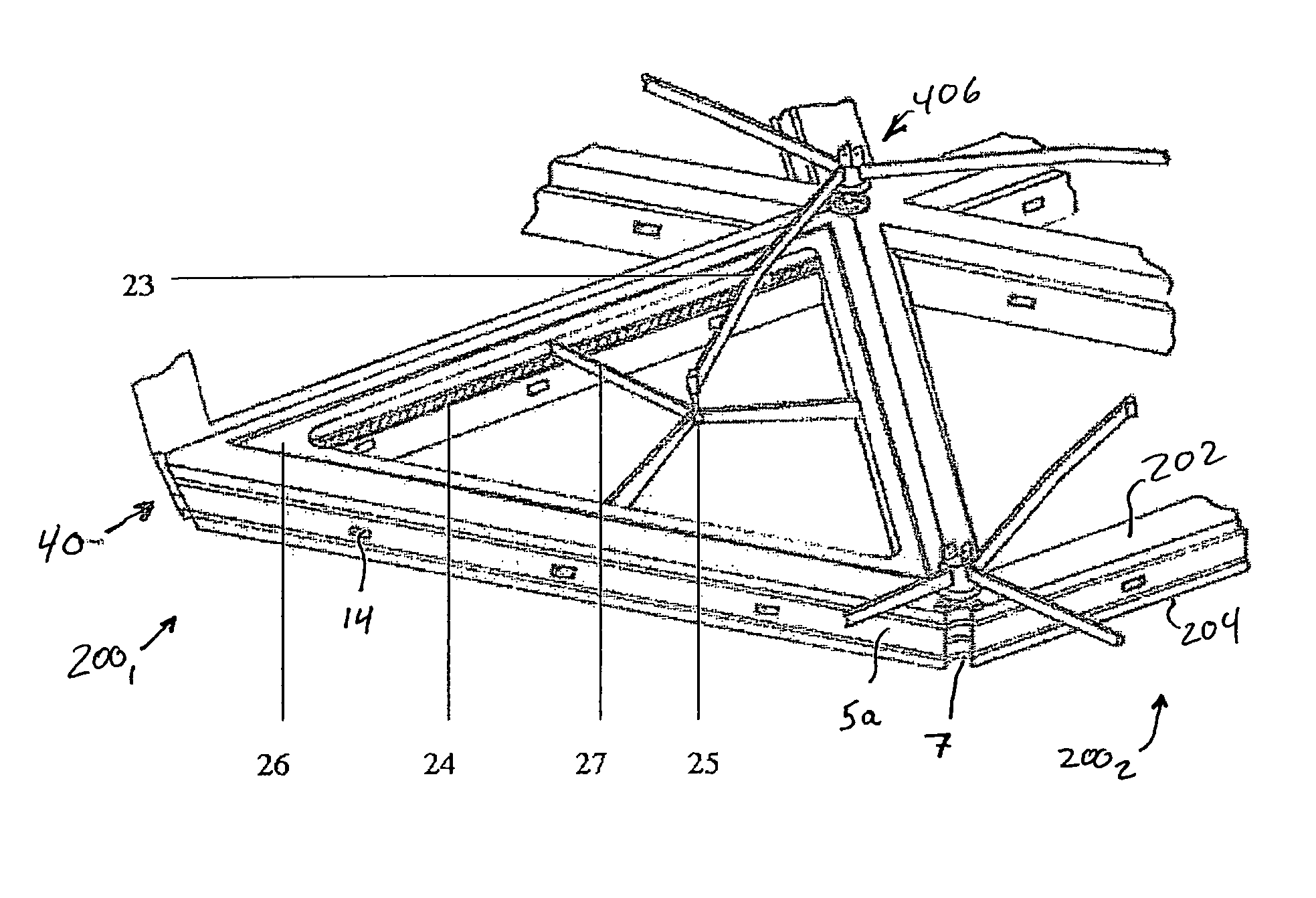
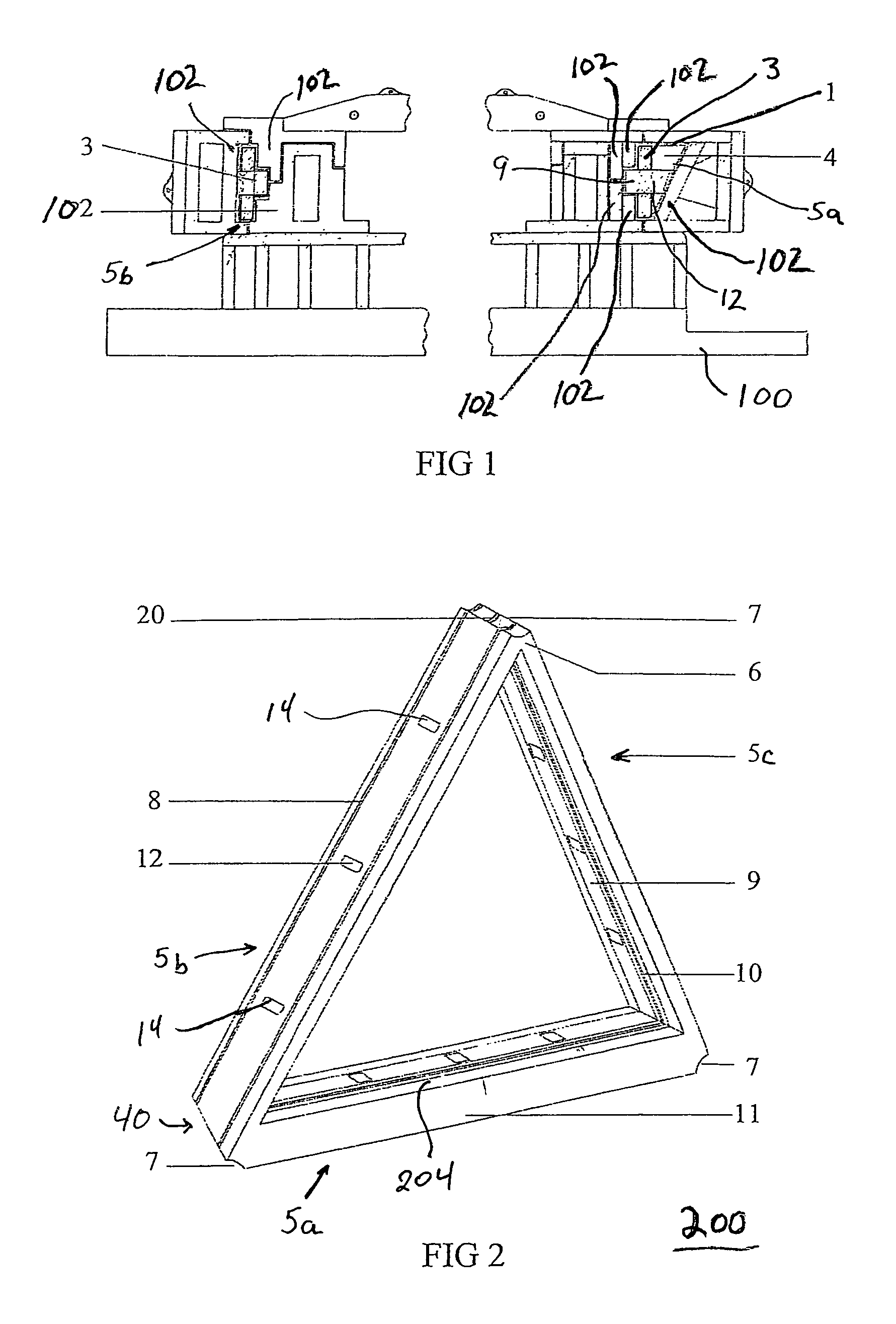
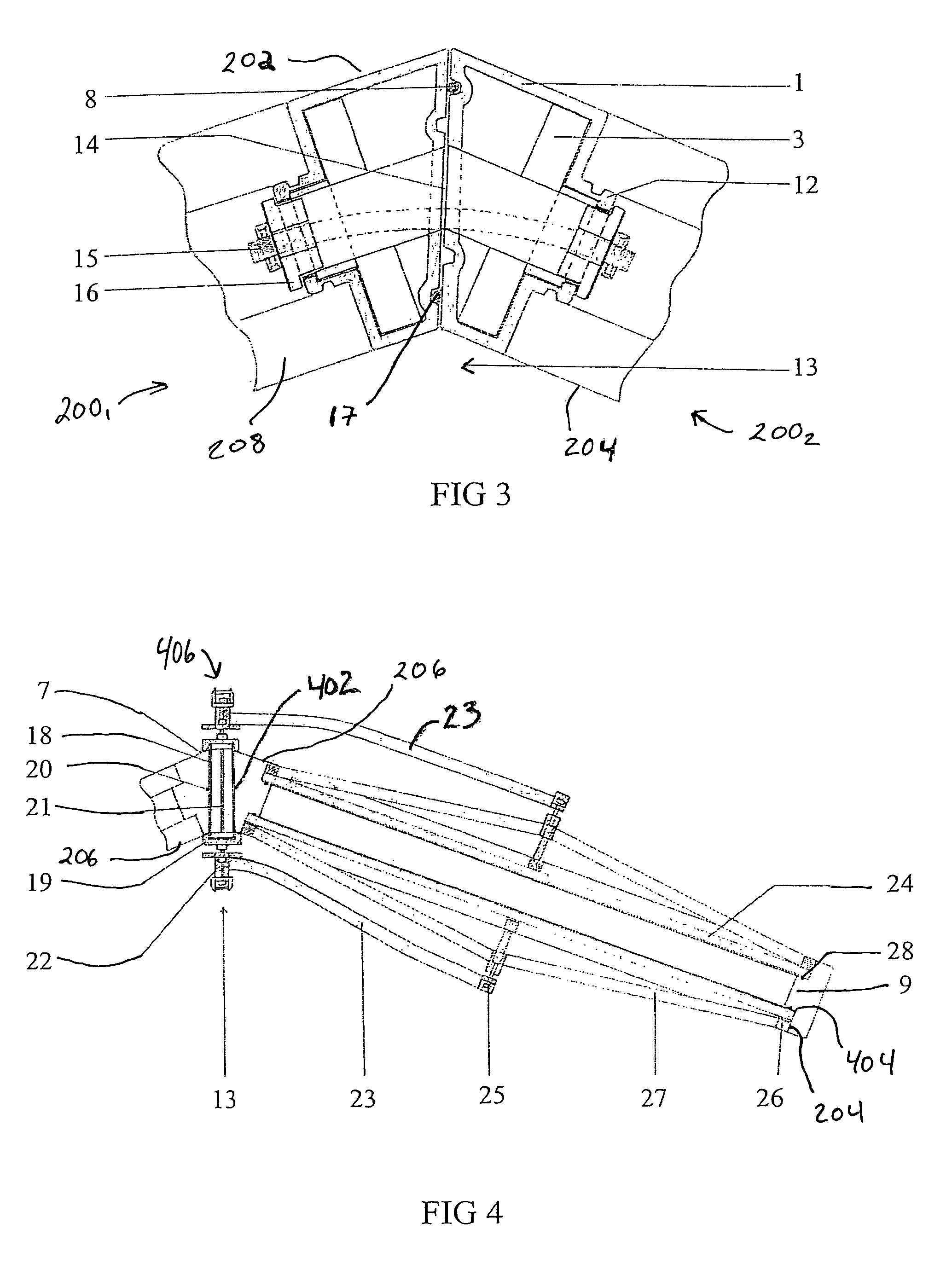
[0038]By reference to those drawings, and particularly FIGS. 1 and 2, each triangular structural element (200) is preferably fabricated using a mould (100). In one embodiment, the process includes coating, with polyester resin layered with fiberglass or with other coating plastic material (1), the inner faces (102) of a mould (100) so as to include all its inner matrix. An elongated section (3), which was previously cut and welded in a template according to the type of triangle (e.g., equilateral, isosceles, right angle) and the height levels chosen, is placed at the bottom of the mould (100). Such section (3) is maintained at a definite distance from the mould walls (102) using the edges provided in the mould walls and penetrating the section. After closing the parts of the mould, an annular cavity (208) is formed between the section (3) and the inner surface of the coating material (1). A polyurethane foam (4) is injected into the cavity (208) to form the three leg members (5a), (...


PUM

PropertyMeasurementUnit
thicknessaaaaaaaaaa
lengthaaaaaaaaaa
lengthaaaaaaaaaa

Abstract

Triangular elements for forming geodesic structures each have three elongated leg members arranged end-to-end to form three apexes. At least one of the apexes is formed with a curved-shaped indentation which extends along an outer surface and perpendicular to the opposing side surfaces. The legs of each triangular element also include one or more outer grooves extending longitudinally along the outer surface. Each outer groove is sized to receive a seal member. An inwardly raised shoulder extends longitudinally along the inner surface. An inner groove is formed along a side edge of the raised shoulder and each inner groove is sized to receive a seal member. Panels are positioned over the opposing sides to form double-walled triangular element. Channels extend through the outer surface and raised shoulder of the inner surface. The triangular elements are arranged to form a geodesic structure and fasteners extend through the channels to secure adjacent triangular elements.

Description

CROSS-REFERENCE TO RELATED APPLICATION[0001]This application claims the benefit under 35 U.S.C. §371 to international application No. PCT / TN2005 / 000004, filed on May 6, 2005.FIELD OF INVENTION[0002]This invention relates to a manufacturing process for executing plane, curvilinear, polyhedral and spherical structures which may be decomposed into a finite number of triangles and more particularly, the present invention relates to a manufacturing process and triangular structures which can be arranged together to form, for example, domes from truncated cone icosahedrons, and chapel-shaped greenhouses.BACKGROUND OF THE INVENTION[0003]Implementation of geodesic domes is conventionally carried out through a series of different shaped triangular structural elements, which can be arranged in a specified pattern based on the frequency of the different shaped triangular structures that are chosen and linked at their tops (i.e., apexes) by knots. Such knots are various connector devices design...

Claims


Application Information

Patent Timeline
Patent Type & Authority Patents(United States)
IPC IPC(8): E04B7/08E04H12/00F16B1/00B29C44/12B29C70/70B29C70/86E04B1/32
CPCB29C70/70B29C70/865Y10T428/24298B29L2031/3002Y10S52/10B29K2705/00
Inventor NEFZI, ABDESSATAR
Owner NEFZI ABDESSATAR
Learn More