Zone catalyzed soot filter

a filter and soot technology, applied in the field of improved catalytic soot filter, can solve the problems of excessive thermal stress and reduce the total effective filter area, and achieve the effect of reducing thermal stress, reducing the effective filtration area, and reducing the effect of thermal stress

Inactive Publication Date: 2010-08-10
DOW GLOBAL TECH LLC
View PDF57 Cites 35 Cited by
  • Summary
  • Abstract
  • Description
  • Claims
  • Application Information

AI Technical Summary

Benefits of technology

[0007]We have discovered an improved catalyzed soot filter that maximizes the effective filtration area while still providing gaseous pollutant abatement. The filter is also able to mitigate temperature differences due to differing species being combusted preferentially along the filter, which surprisingly allows the catalyzed filter to have improved soot combustion and thermal shock resistance than catalyzed filters without zones or with zones where the first zone does not also filter and combust the soot.
[0009]Surprisingly, the catalyzed filter of the invention preferentially captures finer soot particles due to the reduced gas flow through the inlet catalyzed zone while still allowing gaseous pollutant abatement (e.g., HC combustion and CO conversion). The preferential collection of finer soot particles within the inlet end tends to allow for reduced temperature differences during regeneration of the filter (i.e., burnout of the soot), because the entire length of the filter tends to contain a more uniform distribution of soot. In addition, it is believed that the soot in the second zone tends to be comprised of solid particulate soot as opposed to liquid (soot containing hydrocarbon fractions).

Problems solved by technology

Diesel engines, because of the way they operate, emit soot particles or very fine droplets of condensate or a conglomerate of the two (particulates) as well as typical harmful gasoline engine exhausts (i.e., HC and CO).
Each of these suffers from reducing the total effective filter area and excessive thermal stresses due to exaggerated different combustion along the length of the filter.

Method used


Image

  • Zone catalyzed soot filter
  • Zone catalyzed soot filter
  • Zone catalyzed soot filter

Examples


Embodiment Construction

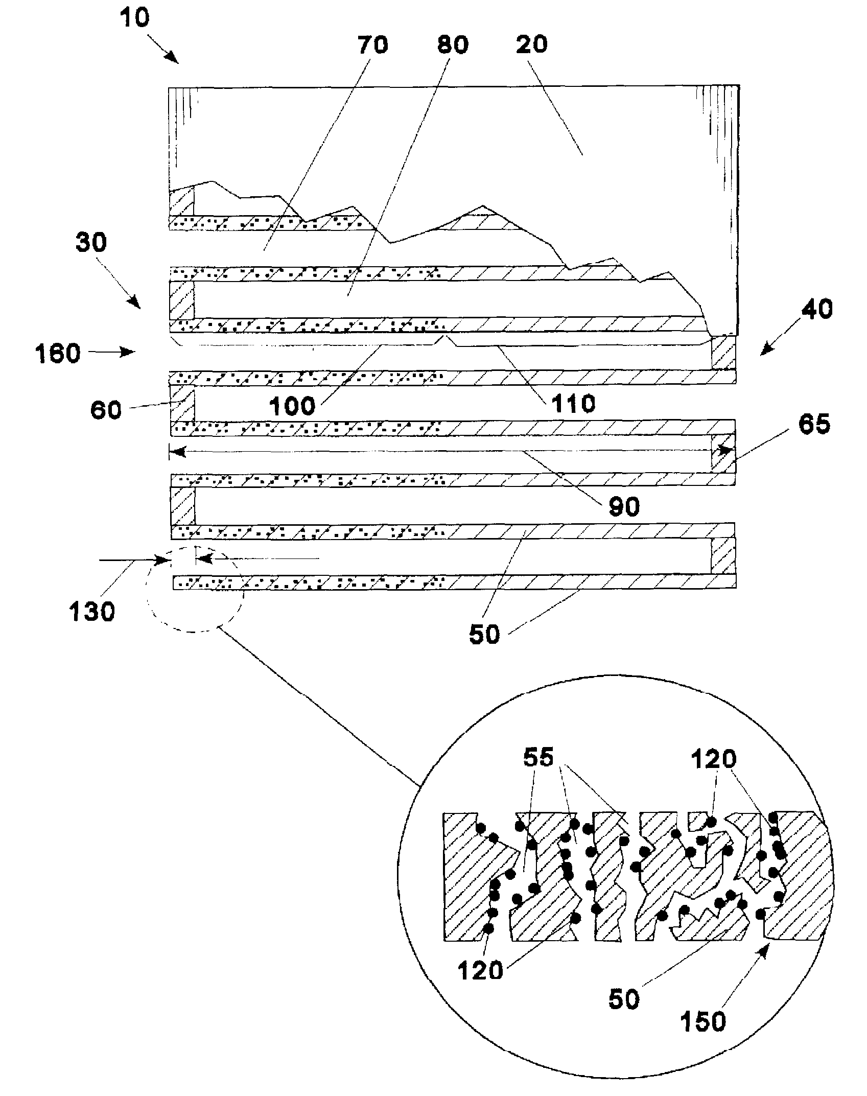
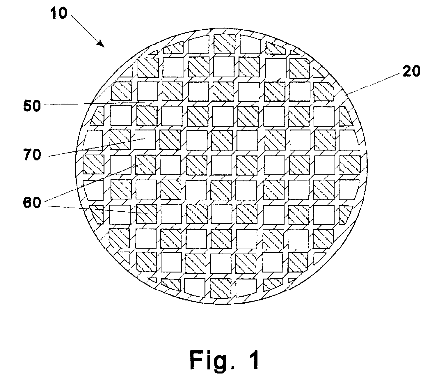
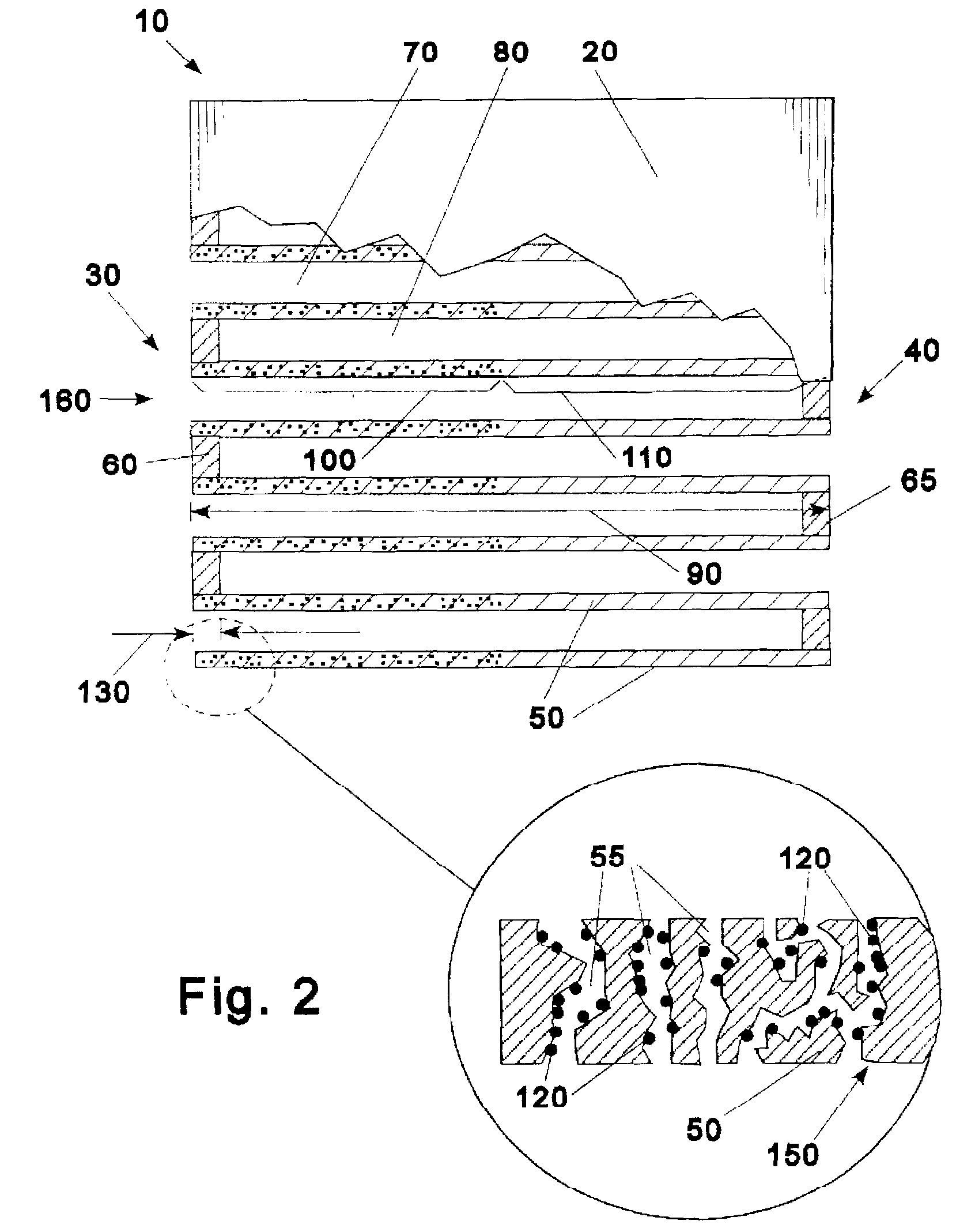
[0015]Referring to the Figures as an illustration, the invention is a catalyzed soot filter 10. The catalyzed soot filter is comprised of a porous ceramic honeycomb 20 having an inlet end 30 and outlet end 40. The honeycomb 20 is comprised of interlaced porous partition walls 50 with inlet plugs 60 and outlet plugs 65, which define inlet channels 70 and outlet channels 80. Along the length 90 of the honeycomb 20 there is an inlet catalyzed zone 100 and an outlet zone 110. In the inlet catalyzed zone 100 there is catalyst 120 within the pores 55 of the partition wall 50 essentially from the inlet end 30 to at most about 45% of the length 90 of the honeycomb 20. Essentially from the inlet end 30 means that the catalyst 120 is within a plug length 130 from the inlet end 30.

[0016]Even though the length of the catalyzed inlet zone 100 may be up to 45% of the length 90 of the honeycomb 20, it is generally not necessary for the zone to be that long. The length of the catalyzed inlet zone 1...


PUM

PropertyMeasurementUnit
porosityaaaaaaaaaa
porosityaaaaaaaaaa
porosityaaaaaaaaaa

Abstract

A catalyzed soot filter is comprised of a monolithic ceramic honeycomb body that has a catalyzed inlet zone that has a catalyst within the walls of the ceramic honeycomb inlet end to at most about 45% of the length of the catalyzed soot filter. The catalyzed inlet zone has a porosity that is at least ⅓ the porosity of a wall of the ceramic honeycomb that does not have a catalyst in the wall.

Description

CROSS-REFERENCE TO RELATED APPLICATIONS[0001]The present application claims the benefit of the filing date of U.S. application Ser. No. 11 / 880,381, filed Jul. 20, 2007, which is hereby incorporated by reference for all purposes. This application also claims the benefit of U.S. Provisional Application No. 60 / 832,580, filed Jul. 21, 2006.FIELD OF THE INVENTION[0002]The present invention relates to an improved catalyzed particulate filter. In particular the invention relates to catalyzed soot filters that have one or more zones of catalysts.BACKGROUND OF THE INVENTION[0003]Diesel engines, because of the way they operate, emit soot particles or very fine droplets of condensate or a conglomerate of the two (particulates) as well as typical harmful gasoline engine exhausts (i.e., HC and CO). These “particulates” (herein Diesel soot), are rich in condensed, polynuclear hydrocarbons, some of which may be carcinogenic.[0004]As the awareness of the danger Diesel soot presents to health collid...

Claims


Application Information

Patent Timeline
Patent Type & Authority Patents(United States)
IPC IPC(8): B01J23/42
CPCB01D46/2429B01D46/2455B01D53/944B01J21/066B01J23/63B01J35/04B01J37/0201B01J37/038F01N3/0222F01N3/035B01D46/2466B01D2046/2433B01D2046/2496B01D2255/1021B01D2255/1023B01D2255/407B01D46/24491B01D46/2498B01D46/2476
Inventor LI, CHENG G.MAO, FUHE
Owner DOW GLOBAL TECH LLC
Why Eureka
Try Eureka