Display device

a display device and display screen technology, applied in the field of display devices, can solve the problems of incorrect input, difficulty in distinguishing a case where a finger or the like is used, etc., and achieve the effect of improving the accuracy of determining

Active Publication Date: 2010-08-10
JAPAN DISPLAY CENTRAL CO LTD
View PDF8 Cites 20 Cited by
  • Summary
  • Abstract
  • Description
  • Claims
  • Application Information

AI Technical Summary

Benefits of technology

[0010]An object of the present invention is to improve accuracy in determining whether or not an object touches a display screen in a display device having an optical input function.
[0012]According to the first aspect of the present invention, for example, the capacitive coupling detector detects the capacitive coupling to an object adjacent to the display screen. Thereby, when the detected capacitive coupling is large, the processor determines that the object touches the display screen, and concurrently calculates the coordinates touched by the object. This makes it possible to improve accuracy in obtaining the timing and the coordinates, at which an object touches a display screen.
[0016]According to the third aspect, the sensor capacitance element and the photosensor, both of which are included in the capacitive coupling detector, are connected to each other in parallel. With this configuration, when an object touches the display screen, the measured potential difference between electrodes of the sensor capacitance element changes according to the timing of measurement, and thereby the output value from the optical input unit changes. For this reason, by detecting a difference between frames with respect to images picked up by the optical input unit, it is possible to detect, as a region touched by an object, a region where the potential difference between the electrodes of the sensor capacitance element changes. In addition, a timing and coordinates at which the object touches the display screen are calculated on the basis of the thus detected region touched by the object. This makes it possible to improve the accuracy of this calculation.
[0018]According to the fourth aspect, the precharge voltage is applied to the first electrode, which is closer to the display screen touched by the object, of the two electrodes of the sensor capacitance element. This facilitates a coupling of the object to the first electrode to which the precharge voltage is applied.
[0019]The first electrode, to which the precharge voltage is applied, preferably has an area larger than the second electrode, from the point of view of facilitating a capacitive coupling of an object to the sensor capacitance element.

Problems solved by technology

However, in the case of such a conventional display device having an optical input function, ambient light conditions such as lighting sometimes makes it difficult to distinguish a case where a finger or the like actually touches a display screen, form a case where the finger or the like is merely in the air above the display screen.
This leads to an incorrect input.

Method used


Image

  • Display device
  • Display device
  • Display device

Examples


Embodiment Construction

[0038]Descriptions will be given below of an embodiment of the present invention by referring to the accompanying drawings.

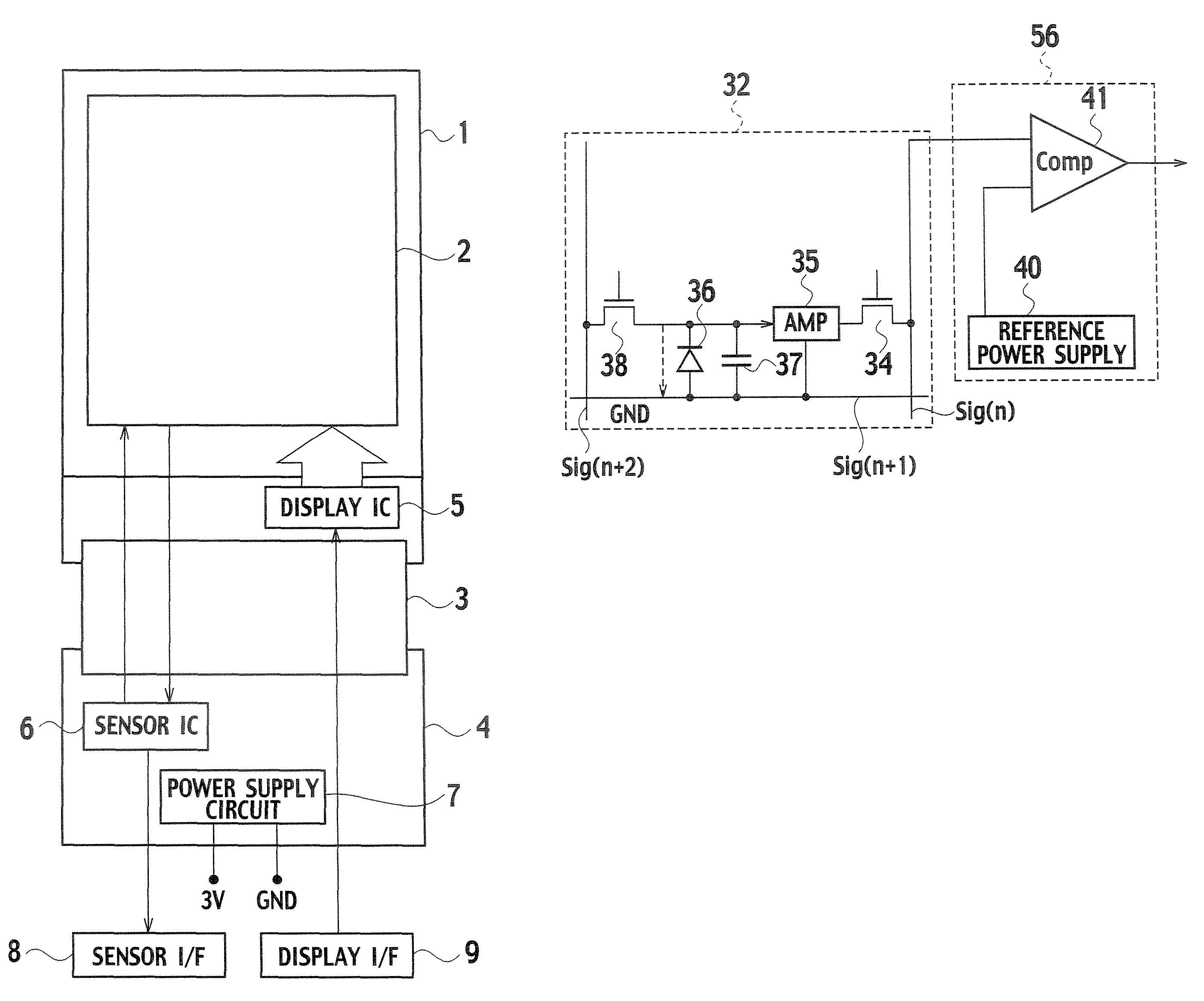
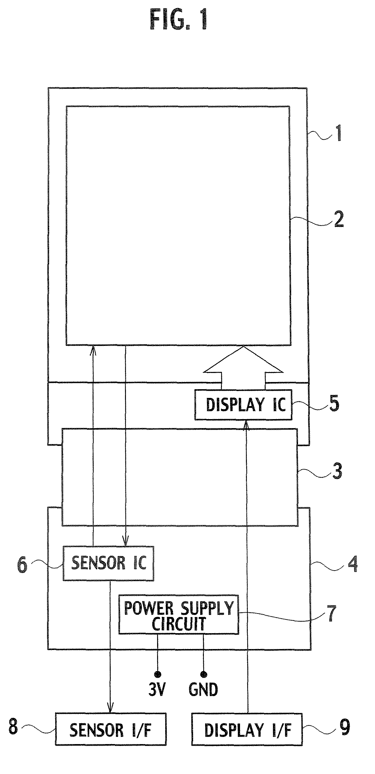
[0039]FIG. 1 is a plan diagram showing a configuration of a display device according to the embodiment of the present invention. The display device shown in FIG. 1 includes a display unit 2, a display IC (Integrated Circuit) 5, a drive substrate 4, a sensor IC 6, a power supply circuit 7, a flexible substrate 3, a display I / F (Interface) 9 and a sensor I / F 8. The display unit 2 is formed on a glass substrate of an array substrate 1. The display IC 5 is mounted on the array substrate 1 by using COG (Chip On Glass). The sensor IC 6 and the power supply circuit 7 are disposed on the drive substrate 4. The flexible substrate 3 connects the array substrate 1 and the drive substrate 4. Incidentally, the sensor IC 6 may be mounted on the array substrate 1 by using COG.

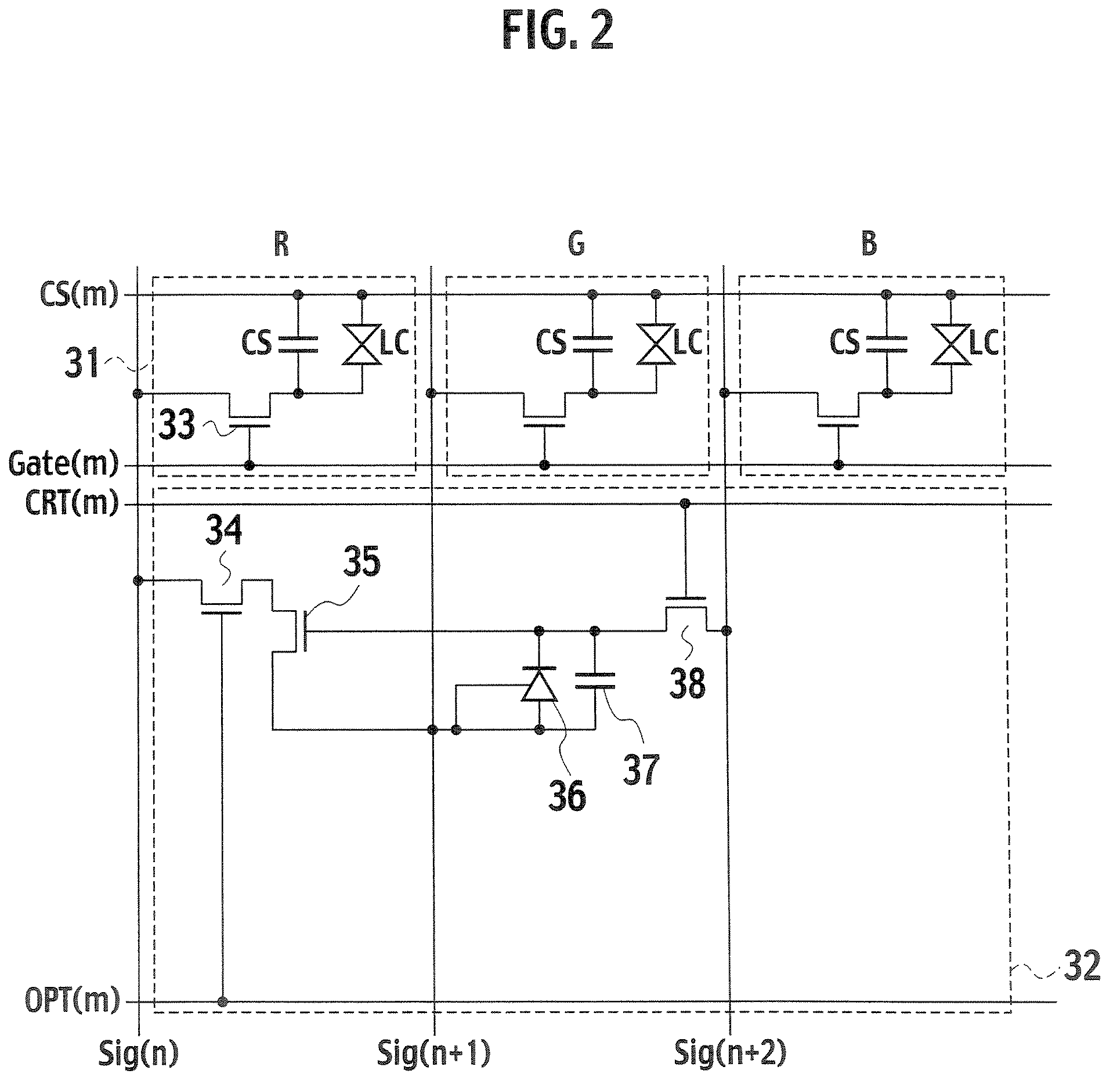
[0040]In the display unit 2, a plurality of scan lines and a plurality of signal lines are arranged so...


PUM


Abstract

In order to improve accuracy in determining whether or not an object touches a display screen, a display device includes a display unit and a processor. The display unit includes an image display unit which displays an image on a display screen, an optical input unit which picks up an image of an object adjacent to the display screen and a capacitive coupling detector which detects a capacitive coupling to the object adjacent to the display screen. The processor determines that the object touches the display screen by using, and concurrently calculates the coordinates touched by the object by using the capacitive coupling detected by the capacitive coupling detector, and the image picked up by the optical input unit.

Description

CROSS-REFERENCE TO RELATED APPLICATIONS[0001]This application is based upon and claims the benefit of priority from Japanese Patent Application No. 2006-200831 filed Jul. 24, 2006; the entire contents of which are incorporated herein by reference.BACKGROUND OF THE INVENTION[0002]1. Field of the Invention[0003]The present invention relates to a display device provided with an optical input function for obtaining information from a display screen by using light.[0004]2. Description of the Related Art[0005]In recent years, as a display device used for various devices such as a cellular phone and a laptop computer, a liquid crystal display device is widely used. In a display unit of a liquid crystal display device, a plurality of scan lines and a plurality of signal lines are arranged so that each scan line intersects each signal lines. In addition, pixels, each of which includes a thin film transistor, a liquid crystal capacitance and an auxiliary capacitance, are provided respectively...

Claims


Application Information

Patent Timeline
Patent Type & Authority Patents(United States)
IPC IPC(8): G09G3/36G06F3/041
CPCG06F3/0354G06F3/044G06F3/0443
Inventor NAKAMURA, TAKASHIIMAI, TAKAYUKIHAYASHI, HIROTAKATADA, NORIONAKAMURA, HIROKI
Owner JAPAN DISPLAY CENTRAL CO LTD
Why Eureka
Try Eureka