Method and system to determine correct tube placement during resuscitation

a tube placement and tube technology, applied in the field of method and system to determine the placement of the correct tube during resuscitation, can solve the problems of failure to secure the tube, failure to recognize the misplacement of the tube, and complications of the victim

Inactive Publication Date: 2010-08-10
LAERDAL MEDICAL AS
View PDF20 Cites 7 Cited by
  • Summary
  • Abstract
  • Description
  • Claims
  • Application Information

AI Technical Summary

Benefits of technology

[0008]It is an object of this invention to provide a method and a system which can provide reliable indications of tube positioning without the abovementioned disadvantages, and which also may be incorporated in existing life saving equipment, such as defibrillators.

Problems solved by technology

Insufficiently trained providers may cause complications to the victim during the procedure.
The following complications are seen: Trauma to oropharynx, ventilation withheld for unacceptably long periods, delayed or withheld chest compressions, esophageal or right mainstem bronchial intubation, failure to secure the tube and failure to recognize misplacement of the tube.
Esophageal intubation is associated with poor outcome, since lung ventilation is inhibited for extended periods of time.
Even with a correctly placed tube, tube dislodgement may happen while the patient is moved.
Dislodgement is related to poorly securing of the tube, and may not be recognized by the paramedics.
This is a difficult skill which needs regular practice to be sensitive.
In the pre-hospital setting it is often complicated due to noise and motion.
End tidal CO2 detectors are also used, but this technique is not well suited for patients in cardiac arrest.
This is a separate device that represents extra cost and the procedure prevents compressions and ventilation from being delivered.
Furthermore, there have been incidents where a esophageal detector device has sucked mucus into the tube, thereby falsely indicating wrong tube placement and preventing use of the tube.
There is also a risk that vomit has entered the airways before intubation, and that vomit can occlude the tube, resulting in false positive detection from the esophageal detector device.

Method used


Image

  • Method and system to determine correct tube placement during resuscitation
  • Method and system to determine correct tube placement during resuscitation
  • Method and system to determine correct tube placement during resuscitation

Examples


Embodiment Construction

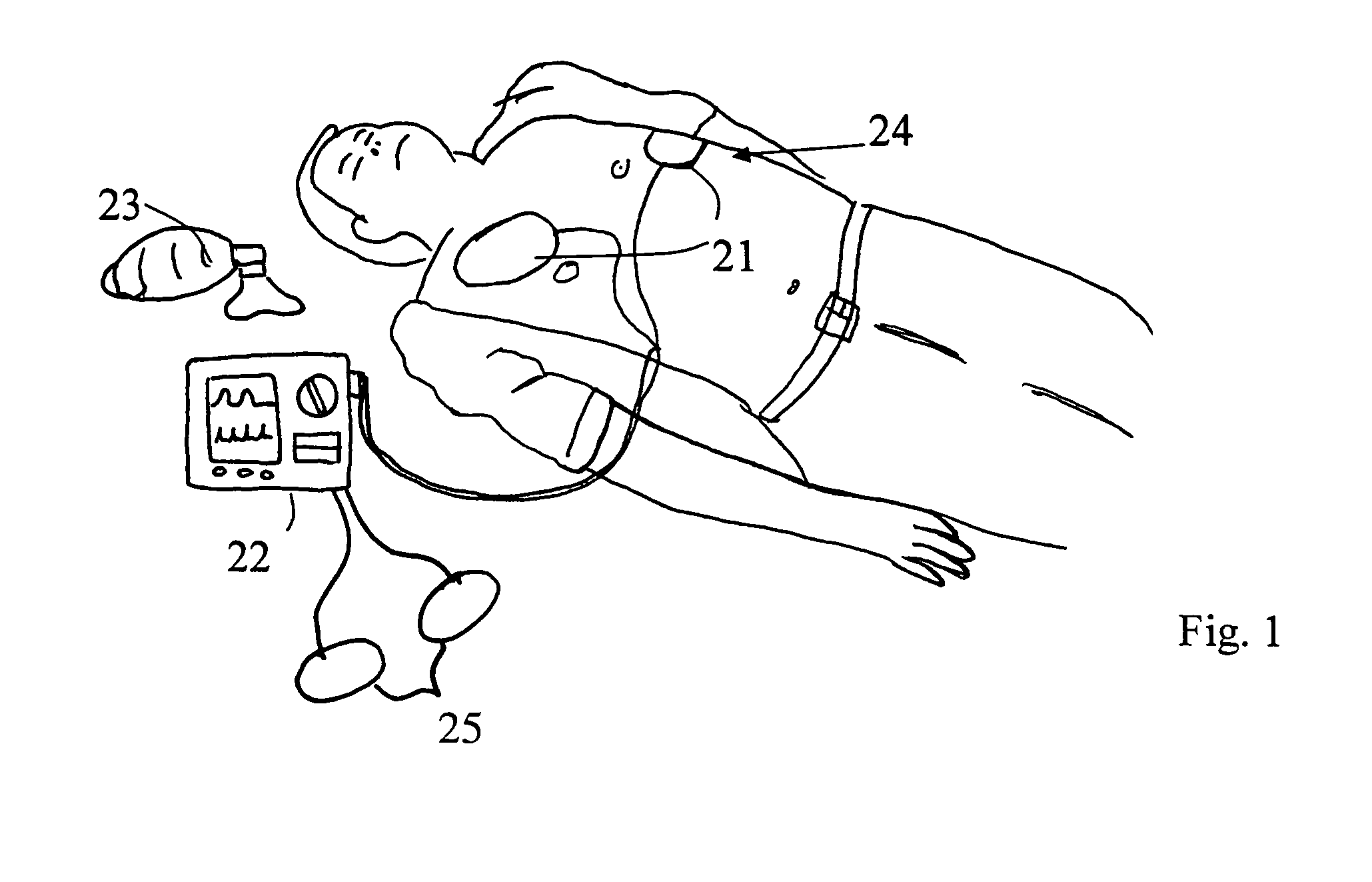
[0021]The system according to the invention, illustrated in FIG. 1 comprises at least two electrodes 21 attached to the patient's thorax 24, an impedance measurement system connected to the electrodes, a microcomputer connected to the impedance measurement system and a display unit connected to the microcomputer, all arranged within a processing unit 22.

[0022]The processing unit 22 illustrated may be provided with visual or acoustic means for providing feedback to the user, e.g. instructing the user in the same way as described in EP 1215993 to retract or adjust the position of the tube or simply be triggering an acoustic warning signal

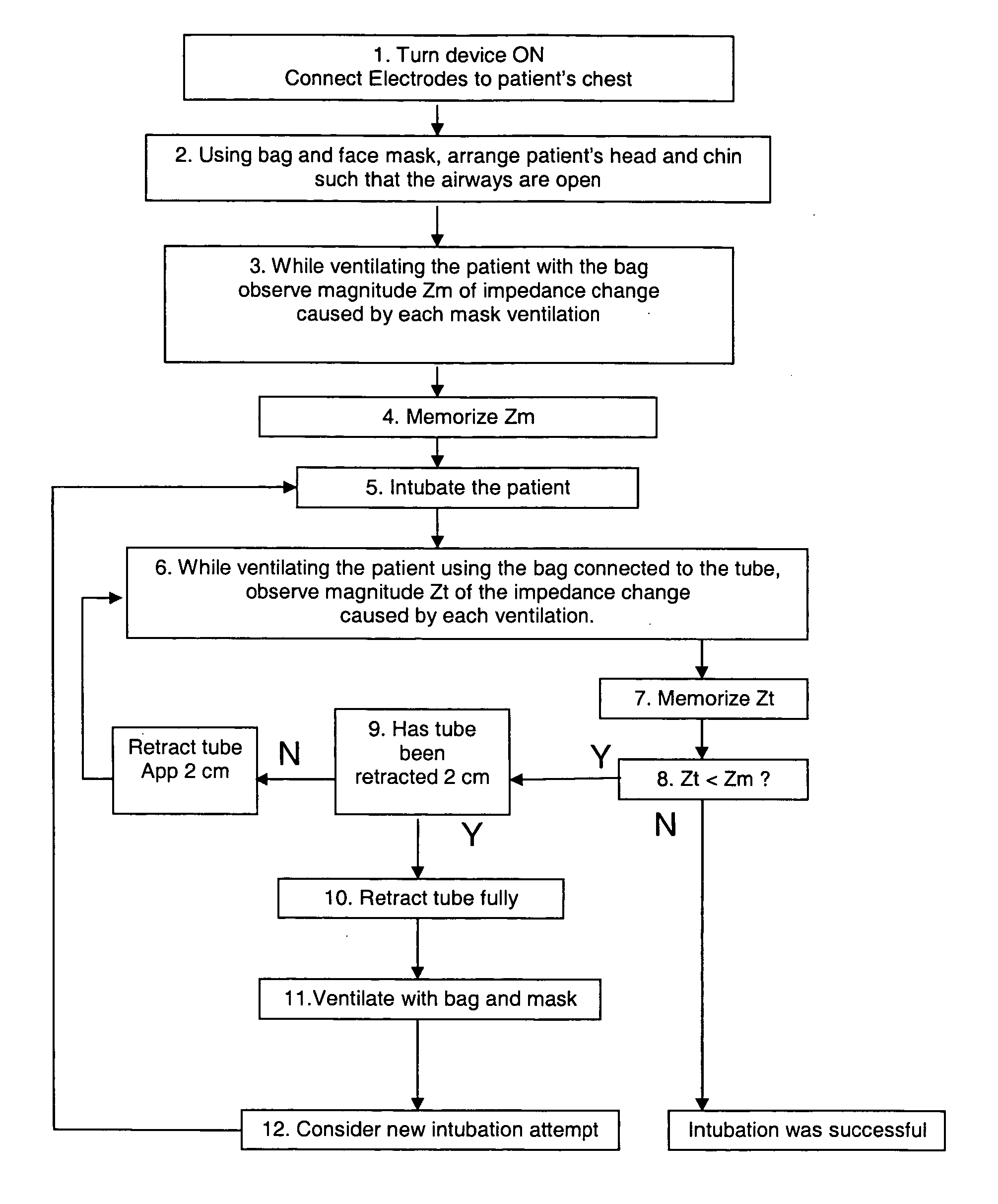
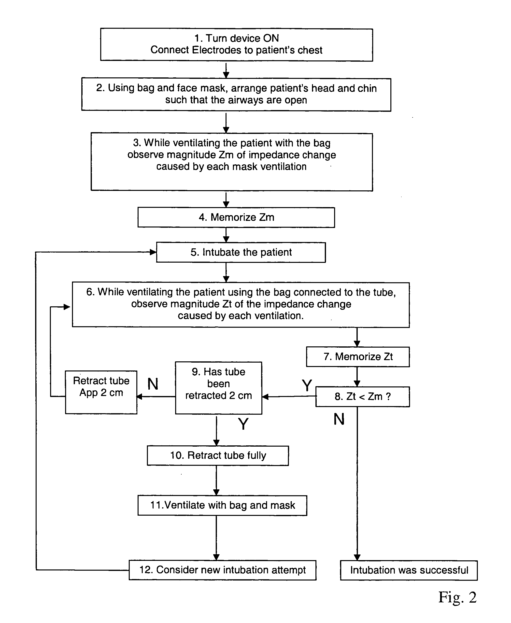
[0023]Referring to FIG. 2 the device according to a preferred embodiment of the invention, is adapted to be used according the following steps:[0024]1. Turn device ON. Connect electrodes 21 to patient's chest 24.[0025]2. Using bag and face mask 23, arrange patients head and chin such that airways are open.[0026]3. While ventilating the patient with th...


PUM


Abstract

System and method for controlling insertion of a tracheal tube in a patient, comprising at least two electrodes adapted to be coupled to the patients chest for providing impedance measurements, a measuring instrument for performing the impedance measurement, said instrument also being provided with storage means for storing a first data set representing chosen characteristics of the impedance change during a first measurement, and evaluation means for comparing the first data set with a second data set representing the characteristics of a second impedance measurement, for evaluating the difference between said measurements and providing an evaluation signal, said first and second data sets representing impedance variations measured during lung inflation with and without an inserted tracheal tube.

Description

[0001]This invention relates to a system and method for determining if a tracheal tube or similar is in a correct position during resuscitation.BACKGROUND OF THE INVENTION[0002]Tracheal intubation is one of several methods to secure the airway during resuscitation, being used especially when a protected airway is lacking. An example of guidelines for performing this is described on pages I-98-1-102 in Guidelines 2000 for Cardiopulmonary Resuscitation and Emergency Cardiovascular Care.[0003]Tracheal intubation is considered a difficult skill in general; See Wang et al “Preliminary experience with prospective, multi-centered evaluation of out-of-hospital endotracheal intubation” Resuscitation 58 (2003) 49-58. Insufficiently trained providers may cause complications to the victim during the procedure. The following complications are seen: Trauma to oropharynx, ventilation withheld for unacceptably long periods, delayed or withheld chest compressions, esophageal or right mainstem bronch...

Claims


Application Information

Patent Timeline
Patent Type & Authority Patents(United States)
IPC IPC(8): A61B5/05A61B5/08A61M16/00A61B5/053A61B5/113
CPCA61B5/0535A61B5/0809A61B5/113A61B5/721
Inventor MYKLEBUST, HELGE
Owner LAERDAL MEDICAL AS
Why Eureka
Try Eureka