Low volumetric compression ratio integrated turbo-compound rotary engine

a rotary engine and low volumetric compression technology, applied in the field of rotary engines and gas turbines, can solve problems such as unsatisfactory airborne applications, and achieve the effects of improving specific power, low volumetric compression ratio, and improving thermal efficiency

Active Publication Date: 2010-08-17
PRATT & WHITNEY CANADA CORP
View PDF33 Cites 197 Cited by
  • Summary
  • Abstract
  • Description
  • Claims
  • Application Information

AI Technical Summary

Benefits of technology

[0007]One general aspect of the present invention covers an integrated cycle topping device and gas turbine engine (the “integrated engine”) designed for low volumetric compression ratio (<3.5) which allows pre-mixed fuel upstream of the cycle topping device without the need of an inter-cooler. It provides for improved thermal efficiency and improved specific power.

Problems solved by technology

Such intercooler are know to be bulky, heavy, etc. and, thus, not ideal for airborne applications.

Method used


Image

  • Low volumetric compression ratio integrated turbo-compound rotary engine
  • Low volumetric compression ratio integrated turbo-compound rotary engine
  • Low volumetric compression ratio integrated turbo-compound rotary engine

Examples


Embodiment Construction

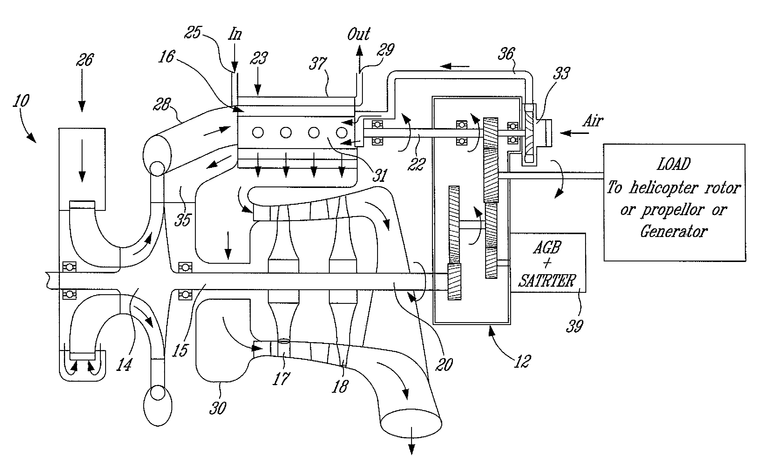
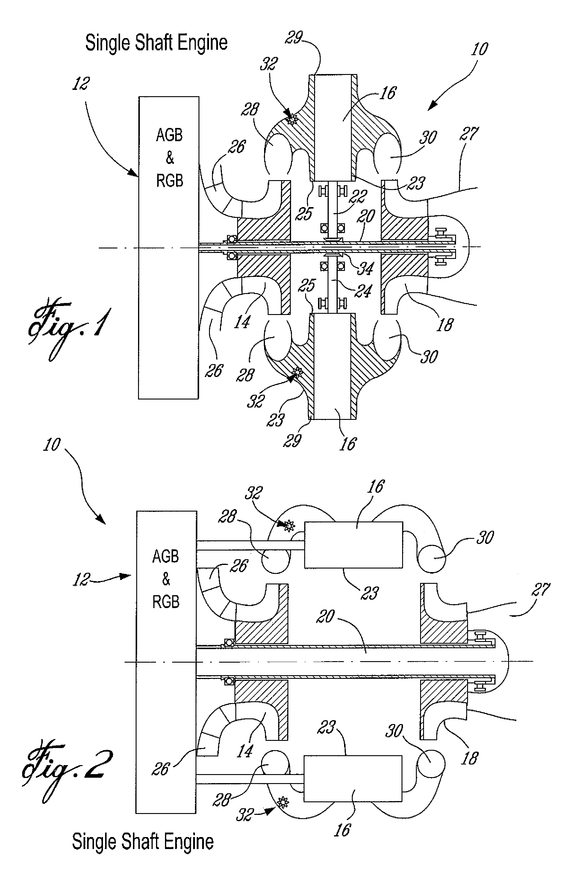
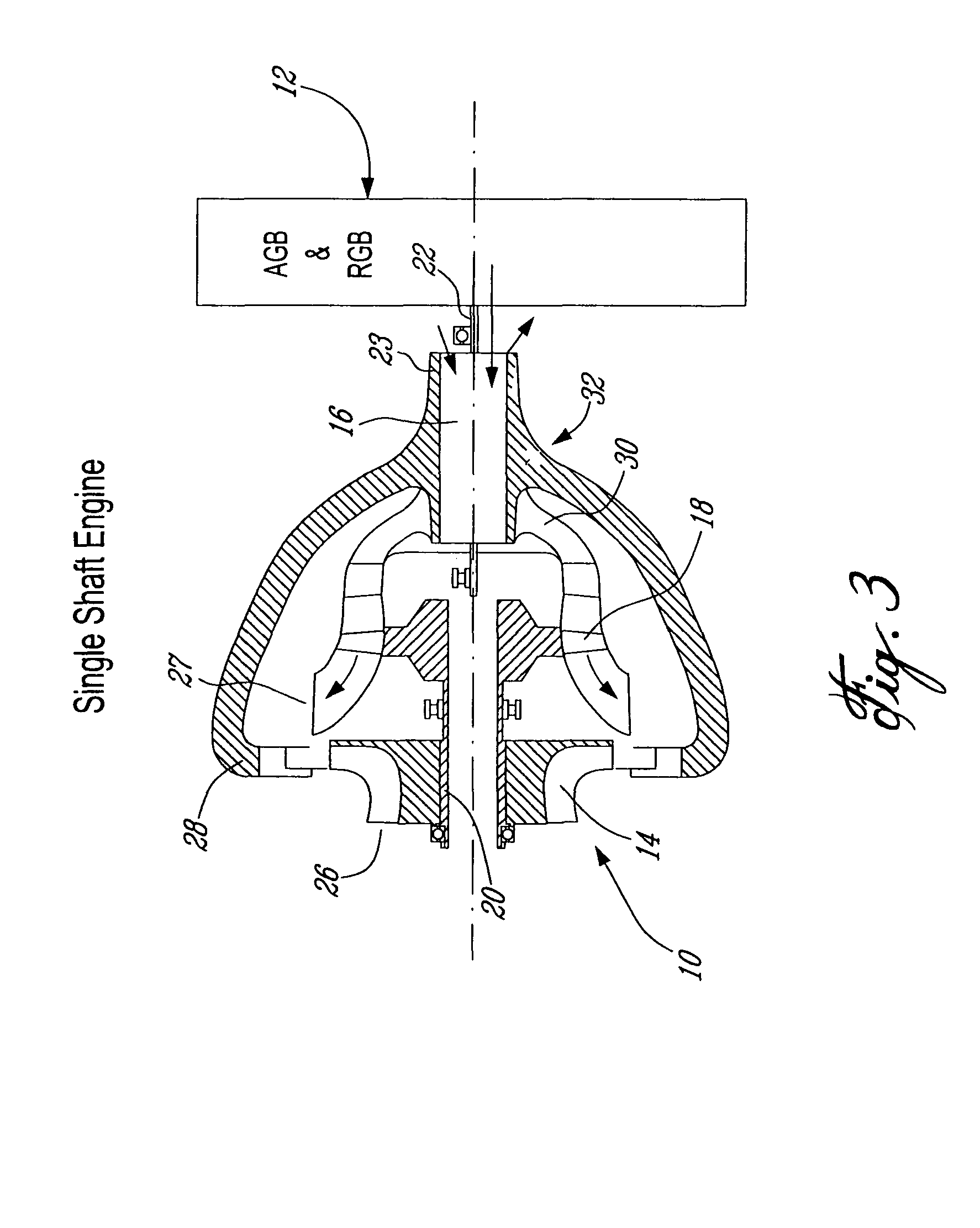
[0021]Integrated engine embodiments are shown in FIGS. 1-3 for single shaft concepts where one (1) or two (2) closed volume combustion rotary engines can be coupled to a power turbine via a gearbox. FIG. 1 shows an integrated engine or compound cycle engine wherein the rotary engines are mounted at 90 degrees to the main engine axis. FIG. 2 shows another possible configuration wherein the rotary engines are mounted parallel to the main engine axis. FIG. 3 shows a rotary engine mounted in-line with the main engine axis.

[0022]Referring now more particularly to FIG. 1, there is disclosed a single shaft engine 10 which includes an AGB / RGB 12 (accessory gearbox / reduction gearbox), a compressor 14, two rotary machines or engines 16 and a power turbine 18 connected on a single shaft 20. The turbine shown is a radial turbine, though other configurations are possible. The rotary engines 16 are connected to the shaft 20 by separate tower shafts 22 and 24. The compressor 14 is preferably a cen...


PUM


Abstract

A compound cycle engine (10) comprises a compressor and a turbine section (14, 18), and at least one cycle topping device (16) providing an energy input to the turbine section (18). The compressor section (14) compresses the air according to a pressure ratio PRgt. The cycle topping device (16) further compresses the air according to a volumetric compression ratio Rvc, and wherein PRgt×Rvc are selected, according to one aspect of the invention, to provide a cycle which permit a more compact and lighter compound cycle engine to be provided.

Description

RELATED APPLICATIONS(S)[0001]This application is a continuation of International Patent Application No. PCT / CA2004 / 000258 filed on Feb. 24, 2004, which claims benefit of Canadian Patent Application No. 2,419,690 filed on Feb. 24, 2003, both of which are herein incorporated by reference.FIELD OF THE INVENTION[0002]The present invention relates to gas turbine and rotary engines and, in particular, to turbo-compounded rotary engines or turbo-compounded internal combustion engine.BACKGROUND OF THE INVENTION[0003]Topping of the gas turbine engine cycle is well-known in the art. U.S. Pat. Nos. 4,815,282, 5,471,834 and 5,692,372, for example, show the prior attempts at integrating gas turbine with cycle-topping devices, such as piston-type internal combustion engines and eccentric rotary engines such as the so-called Wankel engine. Such cycle topping devices promise much-improved fuel efficiency for the integrated engine. All of the integrated engines disclosed in the above mentioned paten...

Claims


Application Information

Patent Timeline
Patent Type & Authority Patents(United States)
IPC IPC(8): F02G3/00F02C3/055F02C3/08F02C3/107F02C5/06F02C6/12
CPCF02C3/055F02C3/08F02C3/107F02C5/06F02C6/12Y02T50/671Y02T50/60
Inventor JULIEN, ANDRECHEVREFILS, ANDRE
Owner PRATT & WHITNEY CANADA CORP
Why Eureka
Try Eureka