Pressure reactive piston for reciprocating internal combustion engine

a technology of internal combustion engine and pressure reactive piston, which is applied in the direction of combustion engine, machine/engine, engine controller, etc., can solve the problems of increasing pm and hc emissions, increasing fuel consumption, and increasing hydrocarbons, so as to reduce nox production, reduce nox production, and reduce the effect of nox production

Inactive Publication Date: 2009-12-29
FORD GLOBAL TECH LLC
View PDF14 Cites 21 Cited by
  • Summary
  • Abstract
  • Description
  • Claims
  • Application Information

AI Technical Summary

Benefits of technology

[0008]The present pressure reactive piston allows beneficial engine operation by reducing peak temperatures and pressures within the combustion chamber, while allowing energy storage in the form of a compression of a gas housed within a gas chamber in the working piston, so as to permit later expansion of the gas and to, in effect, permit operation as if at high compression, but without the attendant formation of NOx, PM, and without the drawback of additional HC resulting from combustion temperatures which are too low.
[0012]According to yet another aspect of the present invention, the static pressure of the compressed gas which is installed within the piston's gas chamber may be selected to be sufficient to prevent the crown from sliding in the compressive direction with respect to the ring portion of the piston during cranking and light load operation of an engine equipped with the piston.
[0013]It is an advantage of the present pressure reactive piston that the benefits of both lower and higher compression ratio are available with a single piston. For example, the benefits of low compression ratio such as low NOx production, lower frictional losses, lower heat losses, and lower mechanical stress to engine components may be had along with the higher thermal efficiency available with a high compression piston, because movement of the piston crown in response to cylinder pressure will effectively result in a reduction in maximum cylinder temperature and maximum cylinder pressure, while nevertheless allowing work done on the compressed gas in the piston to be recaptured when the piston crown moves with respect to the ring portion of the piston during the expansion stroke of the engine.
[0014]It is yet another advantage of a pressure reactive piston according to the present invention that, compared with other variable compression ratio pistons, the present piston is fast acting, but in a repeatable fashion and with more robustness than known pressure active pistons using metallic springs or hydraulic operating systems.

Problems solved by technology

Both of these remedial actions tend, however, to cause increases PM and HC emissions.
This will have the effect of causing cylinder temperature to fall below 1500° K, resulting in higher hydrocarbon, and increased fuel consumption.

Method used


Image

  • Pressure reactive piston for reciprocating internal combustion engine
  • Pressure reactive piston for reciprocating internal combustion engine
  • Pressure reactive piston for reciprocating internal combustion engine

Examples


Embodiment Construction

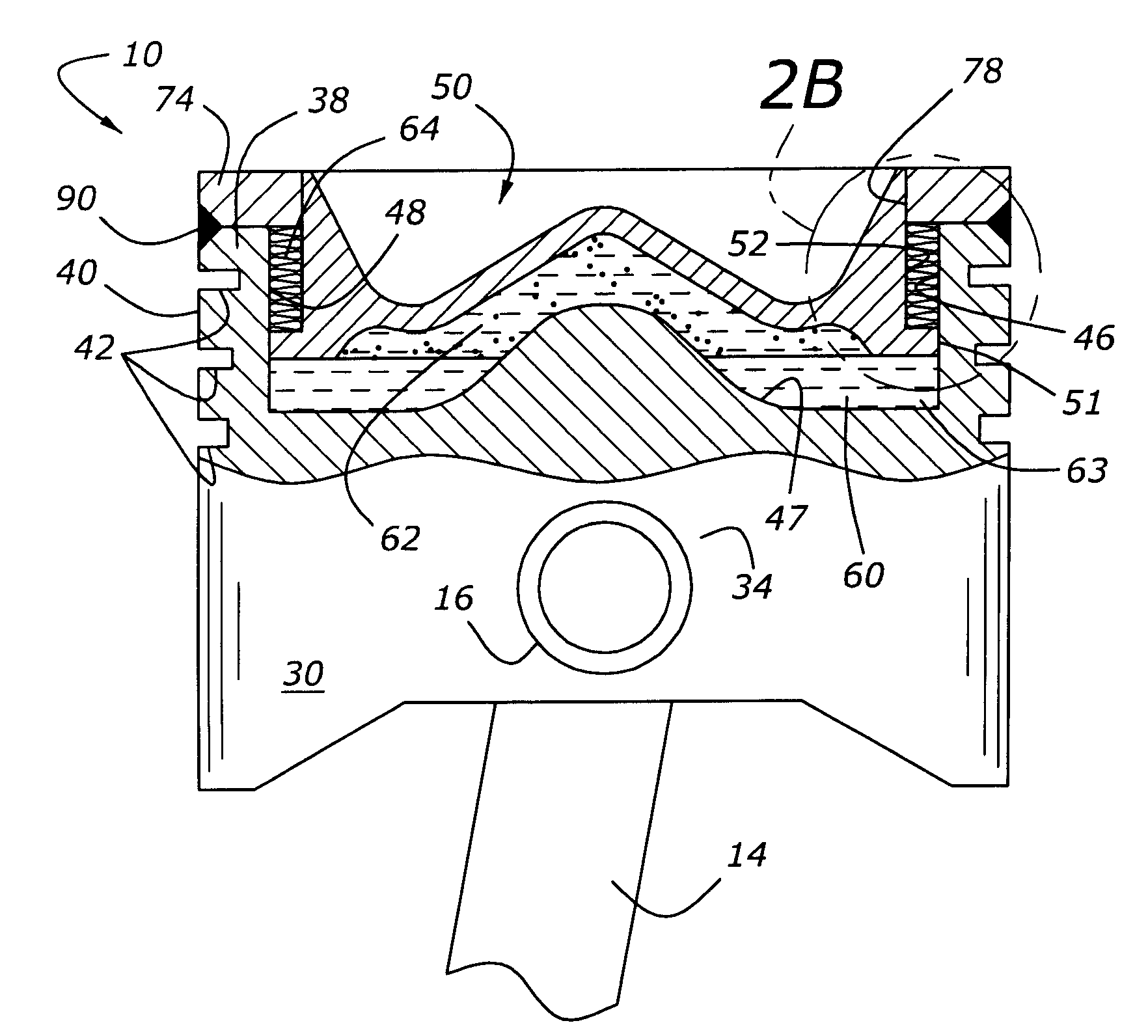
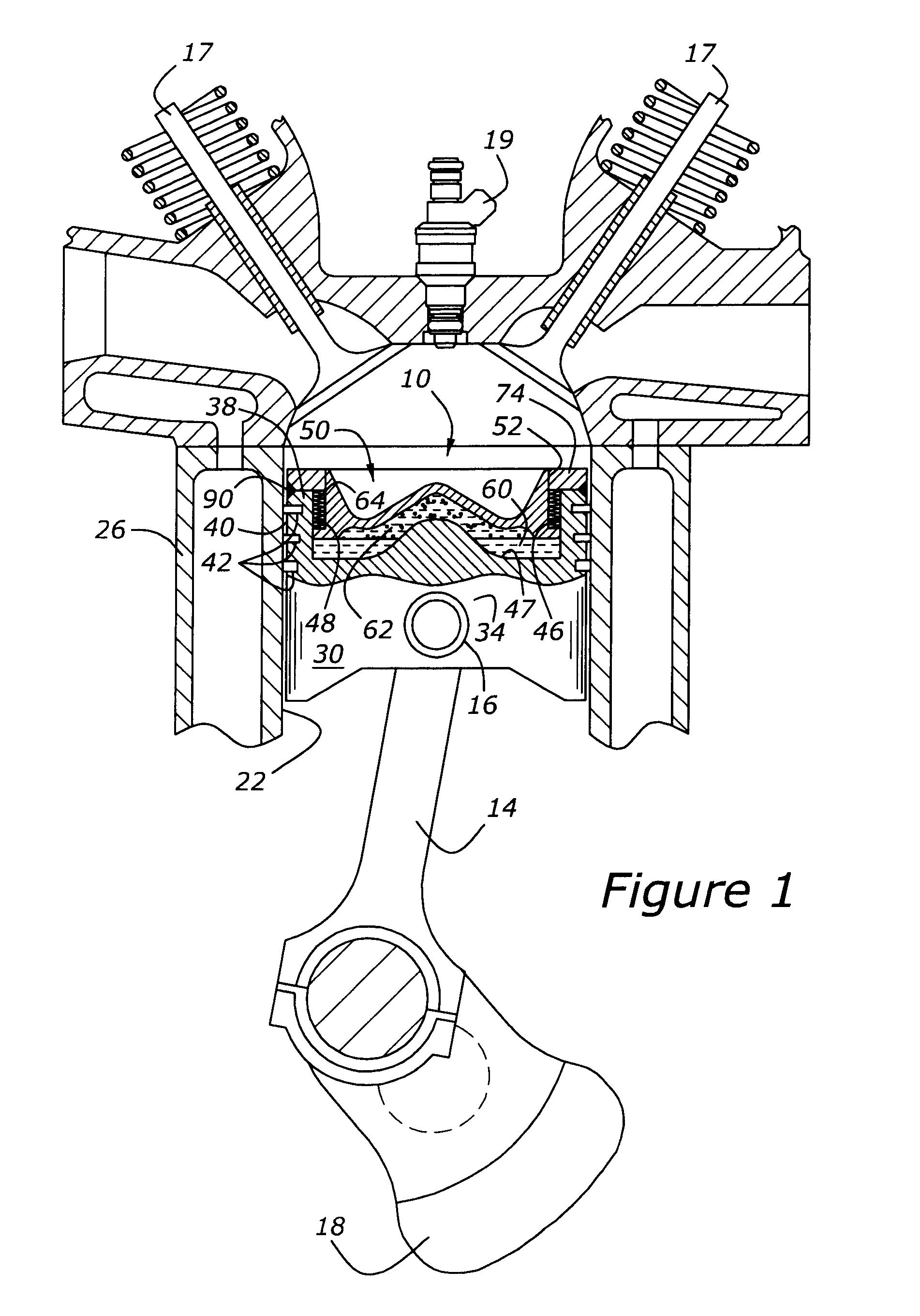
[0022]As shown in FIG. 1, piston 10 is mounted within a cylinder 22, which is carried within a cylinder block, 26. Piston 10 is attached to a connecting rod, 14, by means of a wrist pin, 16. In turn, connecting rod 14 is attached to a crankshaft, 18. The engine also includes poppet valves 17, and a fuel injector, 19. Those skilled in the art will appreciate in view of this disclosure that a piston according to the present invention may be employed with various types of reciprocating internal combustion engines, such as the illustrated diesel, or spark-ignition, or homogenous charge compression ignition (HCCI) engines, or yet other types of reciprocating engines.

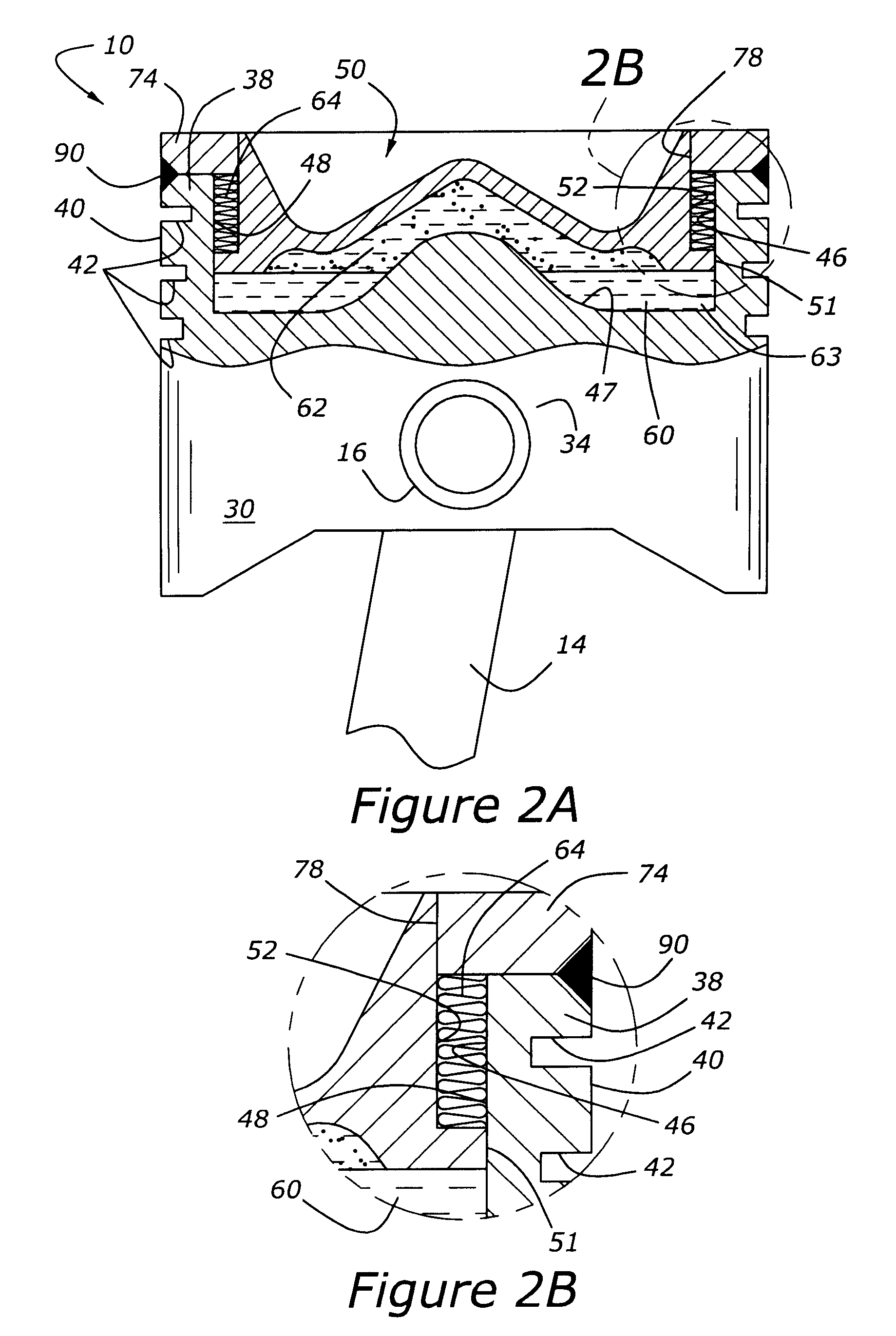
[0023]Piston 10 includes a trunk, 30, which incorporates a wrist pin boss 34. The upper part of the piston includes a ring portion, 38, having an outer wall 40, and a number of piston ring grooves, 42. In the embodiment of FIGS. 1-3B, ring portion 38 is surmounted by an annular top land, 74, having an inner diameter 78, whose...


PUM


Abstract

A pressure reactive piston for an internal combustion engine includes an axially directed central bore formed within a piston ring portion of the piston, which houses a slidably mounted crown which cooperates with the central bore to define a gas chamber which is closed off from the environment by means of a flexible gas seal interposed between the crown and the ring portion of the piston.

Description

CROSS REFERENCE TO RELATED APPLICATIONS[0001]None.BACKGROUND OF THE INVENTION[0002]1. Field of the Invention[0003]The subject matter disclosed herein relates to a piston for use in a reciprocating internal combustion engine. The piston has a slidably mounted crown forming part of a gas chamber at the top of the piston. The gas chamber acts as a gas spring to suspend the piston crown.[0004]2. Related Art[0005]Designers of reciprocating internal combustion engines, in general and, more specifically, diesel engines, are faced with increasingly stringent regulatory requirements relating to exhaust emissions. More specifically, future regulations will require less emission of oxides of nitrogen (NOx), particulate matter (PM), and unburned hydrocarbons (HC). It is known that an effective way to control NOx is to decrease the peak temperatures within the combustion chamber, as well as by decreasing the available oxygen through exhaust gas recirculation (EGR). Both of these remedial actions...

Claims


Application Information

Patent Timeline
Patent Type & Authority Patents(United States)
IPC IPC(8): F02F3/00
CPCF02B75/044F02F3/18F02F3/0015F02F3/28F02B1/12F02B23/0696F02D15/04F02B2275/14F02B75/36
Inventor STYRON, JOSHUA P.
Owner FORD GLOBAL TECH LLC
Why Eureka
Try Eureka