
Method for purification of nitrogen oxide and apparatus for purification of nitrogen oxide

a technology of nitrogen oxide and purification method, which is applied in the direction of nitrogen oxide/oxyacid, nitrous oxide, separation process, etc., can solve the problems of complex system containing nitrogen oxide, serious safety problems, and difficulty in executing ultra-low temperature steps, so as to achieve efficient purification of nitrogen oxide and high safety

Active Publication Date: 2010-08-17
SUMITOMO SEIKA CHEM CO LTD
View PDF15 Cites 42 Cited by
  • Summary
  • Abstract
  • Description
  • Claims
  • Application Information

AI Technical Summary

Benefits of technology

[0006]An object of the present invention is to provide a method of purifying a nitrogen oxide appropriate for efficiently purifying the nitrogen oxide with high safety.
[0007]Another object of the present invention is to provide an apparatus that purifies a nitrogen oxide, appropriate for efficiently purifying the nitrogen oxide with high safety.

Problems solved by technology

Accordingly, a system containing the nitrogen oxide tends to be complicated, in terms of the type and amount of the nitrogen oxides involved.
The nitrogen oxide is what is known as an endothermic compound, and executing the ultra-low temperature step is problematic from the viewpoint of safety, because it is known that the condensed nitrogen oxide may even explode from an impact, depending on the condition.
Especially, the impact sensitivity of liquefied NO with respect to explosion probability is close to that of nitroglycerin, and therefore purification of NO by distillation presents a serious problem in the aspect of safety.
When purifying a target nitrogen oxide with the separation technique employing the zeolite adsorbent, however, the larger number of nitrogen oxide species the source gas contains, the more types of zeolite adsorbents have to be employed, and in many cases the number of columns also has to be increased, which makes the purification system complicated.
Such technique often fails to efficiently purify a nitrogen oxide (often contained in a multicomponent system before the purification).

Method used

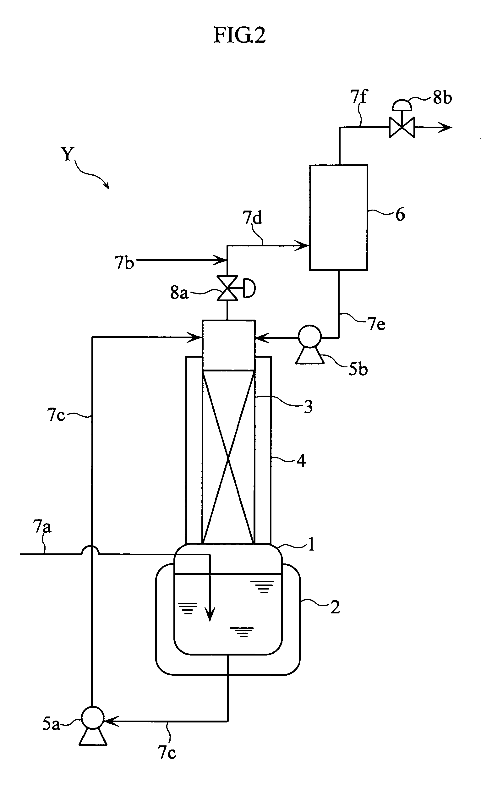

Image

  • Method for purification of nitrogen oxide and apparatus for purification of nitrogen oxide
  • Method for purification of nitrogen oxide and apparatus for purification of nitrogen oxide
  • Method for purification of nitrogen oxide and apparatus for purification of nitrogen oxide

Examples


example 1

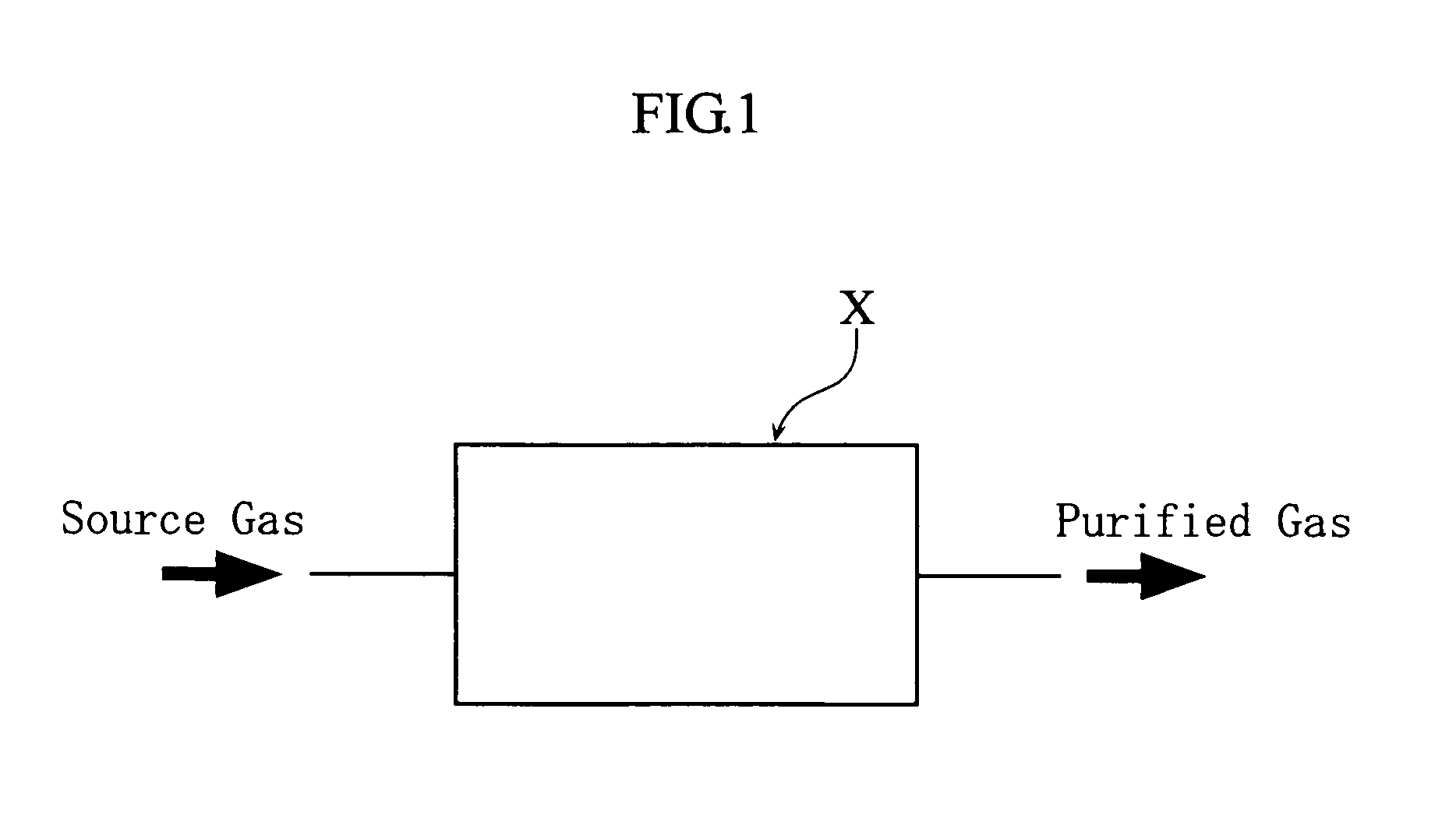
[0059]As the example 1, the NO purification method was executed with the condenser X shown in FIG. 1. In this example, a glass trap (500 cm3) cooled to −80° C. was employed as the condenser X, and raw NO gas containing 5000 ppm of NO2 as the source gas, and such source gas was supplied through the condenser X at a rate of 100 cm3 / minute (condensation-separation step). As a result, N2O3 and N2O4 generated from NO and NO2 in the source gas were condensed in the condenser X, and NO2 concentration in the purified NO gas led out of the condenser X was 80 ppm.

example 2

[0060]As the example 2, the N2O purification method was executed with the condenser X shown in FIG. 1. In this example, a glass trap (500 cm3) cooled to −80° C. was employed as the condenser X, and raw N2O gas containing 2000 ppm of NO as the source gas. In this example, firstly NO2 was added to the source gas to achieve a final concentration of 2000 ppm (concentration adjustment step). Then the source gas subjected to such concentration adjustment was supplied through the condenser X at a rate of 100 cm3 / minute (condensation-separation step). As a result, N2O3 and N2O4 generated from NO and NO2 in the source gas were condensed in the condenser X, and NO concentration in the purified N2O gas led out of the condenser X was 50 ppm, and NO2 concentration was 30 ppm.

example 3

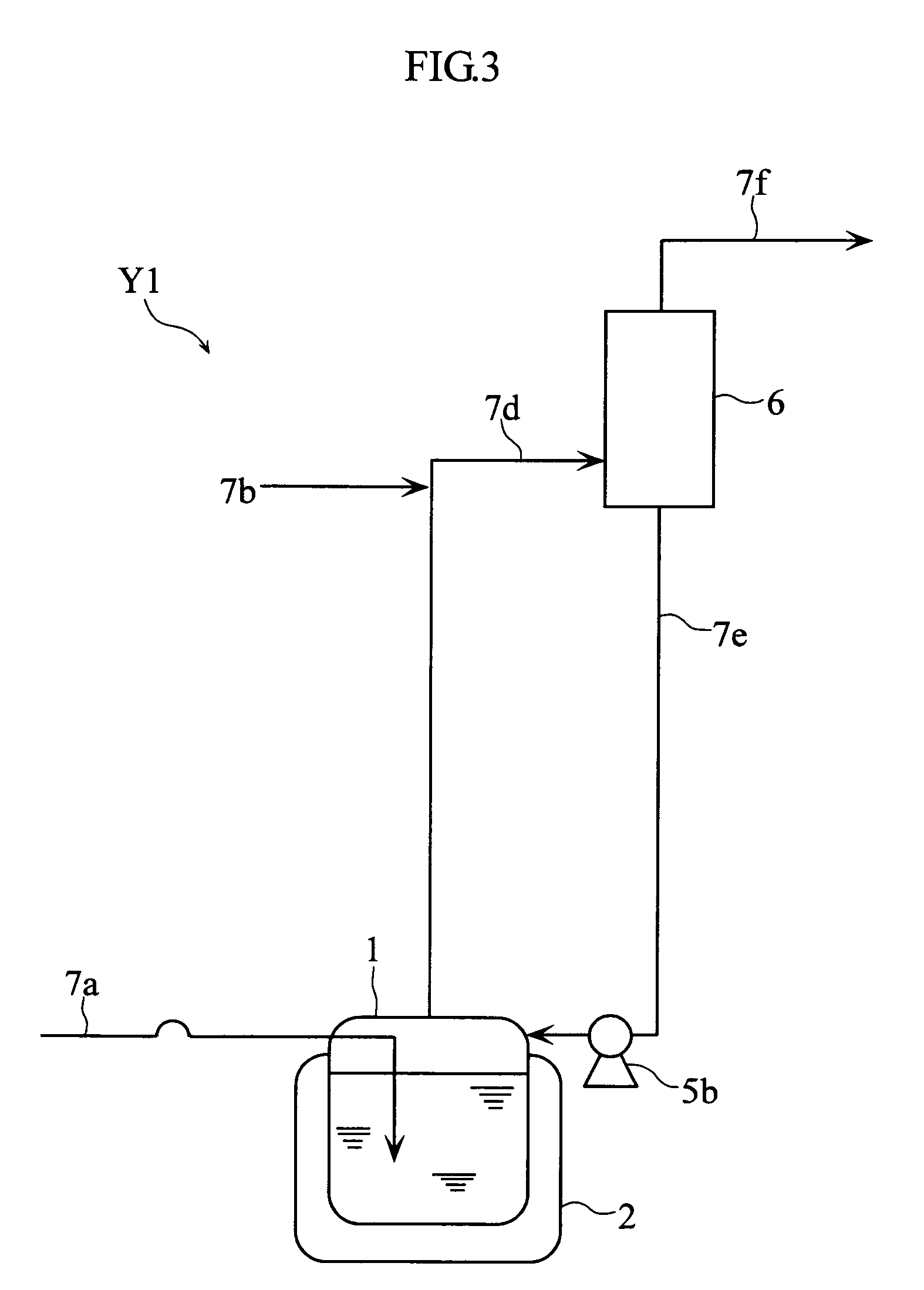
[0061]As the example 3, the NO purification method was executed with the condenser Y1 shown in FIG. 3. In this example, a container (500 cm3) cooled to −10° C. was employed as the gas absorption vessel 1, a glass trap (500 cm3) cooled to −70° C. as the condenser 6, liquefied N2O4 (90 g) as the absorption solution, and raw NO gas containing 1000 ppm of N2 and 1000 ppm of N2O as the source gas.

[0062]In this example, the absorption step and the revaporization step in the gas absorption vessel 1, as well as the condensation-separation step in the condenser 6 were executed. In the absorption step, the liquefied N2O4 (90 g, −10° C.) was caused to absorb 32 g of source gas under normal pressure. In the revaporization step, the internal temperature in the gas absorption vessel 1 was gradually raised from −10° C. to 2° C. In the condensation-separation step, the gas evaporated in the revaporization step was supplied through the condenser 6, to produce condensed N2O3 and N2O4 gas generated fr...


PUM

PropertyMeasurementUnit
boiling pointaaaaaaaaaa
melting pointaaaaaaaaaa

Abstract

A nitrogen oxide purifying apparatus includes a gas absorption vessel (1) and a condenser (6), where the vessel receives an absorption solution containing liquefied N2O4 for absorbing NO and also receives a source gas to vary the temperature and / or pressure of the source gas and the absorption solution, while the condenser receives a gas from the gas absorption vessel (1) to vary the temperature and / or pressure of the gas. In the gas absorption vessel (1), the absorption solution containing liquefied N2O4 may be applied to the source gas containing NO, so that NO is absorbed in the absorption solution. Then the absorption-solution is heated and / or depressurized to generate an intermediate gas containing a relatively large amount of NO and a smaller amount of NO2 from the absorption solution. In the condenser (6), the intermediate gas is cooled and / or pressurized to give condensed N2O3 and / or condensed N2O4.

Description

TECHNICAL FIELD[0001]The present invention relates to a method and apparatus for purifying a nitrogen oxide, such as nitrogen monoxide, nitrogen dioxide, or nitrous oxide.BACKGROUND ART[0002]The nitrogen element can have an atomic value varying from monovalent to pentavalent, and there are many types of nitrogen oxides (usually in a gas state under a normal temperature and normal pressure), such as nitrous oxide (N2O), nitrogen monoxide (NO) and nitrogen dioxide (NO2). Also, a nitrogen oxide can be easily reacted with another nitrogen oxide, thereby giving a new nitrogen oxide. Accordingly, a system containing the nitrogen oxide tends to be complicated, in terms of the type and amount of the nitrogen oxides involved. For example, upon manufacturing NO through an ammonia oxidation method, which is a popular industrial manufacturing method thereof, N2O, NO2, and N2 are generated as by-products in addition to the desired NO, and mixed in the NO gas as impurities.[0003]To increase the p...

Claims


Application Information

Patent Timeline
Patent Type & Authority Patents(United States)
IPC IPC(8): C01B21/20
CPCC01B21/36C01B21/24C01B21/22
Inventor HATA, HIROYUKIHAMADA, KENJITAI, SHINICHI
Owner SUMITOMO SEIKA CHEM CO LTD
Learn More