
Signal-to-noise ratio measurement for discrete waveform

a signal-to-noise ratio and discrete waveform technology, applied in the direction of noise figure or signal-to-noise ratio measurement, instruments, transmission monitoring, etc., can solve the problems of noise degrading snr, no method and apparatuses have been known which can measure, and expensive special measuring equipmen

Active Publication Date: 2010-08-17
ADVANTEST CORP
View PDF4 Cites 1 Cited by
  • Summary
  • Abstract
  • Description
  • Claims
  • Application Information

AI Technical Summary

Benefits of technology

Enables accurate measurement of jitter and ENOB in AD converters, even at high frequencies, with the capability to calculate both RMS and peak-to-peak values, improving the assessment of AD converter performance and providing feedback for design improvements.

Problems solved by technology

This necessitates expensive special measuring equipment for the measurement.
Such varieties of noise degrade the SNR.
However, no methods and apparatuses have been known which can measure the ENOB due only to the jitter component.
Therefore, it is difficult to accurately isolate the jitter component contained in the noise component from the quantization noise component in the noise component.
Additionally, since the above method calculates the jitter based on the energies of the noise components contained in the spectra, the above method can only calculate the RMS value of the jitter, but cannot calculate the change in the instantaneous value of the jitter such as the peak value and the peak-to-peak value, and the aperture jitter waveform.
Therefore, it is difficult to provide feedback data to the design of the AD converter.

Method used


Image

  • Signal-to-noise ratio measurement for discrete waveform
  • Signal-to-noise ratio measurement for discrete waveform
  • Signal-to-noise ratio measurement for discrete waveform

Examples


Embodiment Construction

[0086]Some aspects of the invention will now be described based on embodiments, which do not intend to limit the scope of the present invention, but exemplify the invention. All of the features and the combinations thereof described in the embodiments are not necessarily essential to the invention.

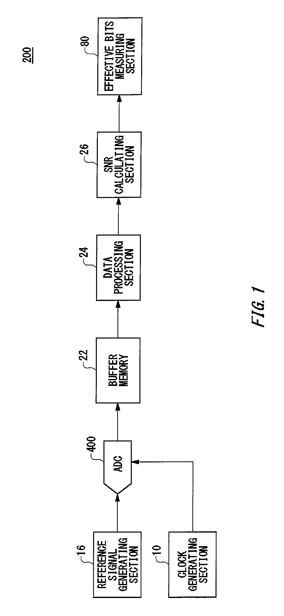
[0087]FIG. 1 illustrates an exemplary configuration of a measuring apparatus 200 relating to an embodiment of the present invention. The measuring apparatus 200 is configured to measure jitter which may be generated by an AD converter 400. The measuring apparatus 200 includes therein a reference signal generating section 16, a clock generating section 10, a buffer memory 22, a data processing section 24, an SNR calculating section 26, and an effective bits measuring section 80.

[0088]The reference signal generating section 16 generates an analog reference signal as an input signal to be applied to the AD converter 400. The reference signal generating section 16 may generate a periodic signa...


PUM


Abstract

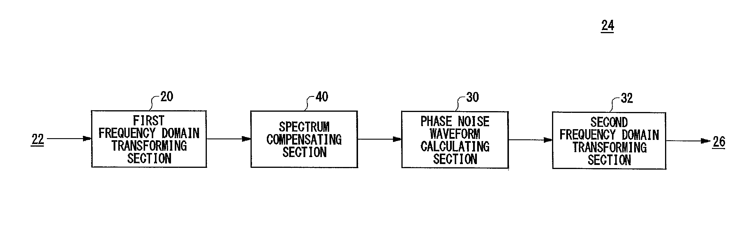
There is provided a measuring apparatus for measuring a signal-to-noise ratio of a discrete waveform which is output from an AD converter in response to an input signal, where the signal-to-noise ratio indicates a ratio of a signal component of the input signal to noise generated by the AD converter. The measuring apparatus includes a spectrum compensating section that receives a spectrum of the discrete waveform output from the AD converter, and compensates the received spectrum in accordance with a non-symmetric sideband between an upper sideband and a lower sideband of the received spectrum, where the upper and lower sidebands are defined with respect to a fundamental frequency of the input signal, and a phase noise waveform calculating section that calculates a phase noise waveform of the discrete waveform based on the spectrum which has been compensated by the spectrum compensating section.

Description

BACKGROUND[0001]1. Technical Field[0002]The present invention relates to a measuring apparatus, a test apparatus, a recording medium, a program and an electronic device. More particularly, the present invention relates to a measuring apparatus for measuring jitter of a signal under measurement, and to a measuring apparatus for measuring jitter generated by an AD converter.[0003]2. Related Art[0004]One of the methods to measure jitter generated by an AD converter is to input an input signal and a sampling clock into the AD converter and measure jitter included in the output from the AD converter. Here, the input signal is a sine wave with small jitter, for example, and the sampling clock also has small jitter. The jitter generated by the AD converter represents, for example, the variance in the aperture delay from the zero cross timing of the sampling clock at which a start conversion command is given to the moment at which the level of the input signal is held. This jitter is also r...

Claims


Application Information

Patent Timeline
Patent Type & Authority Patents(United States)
IPC IPC(8): G01R29/26
CPCH04B17/336
Inventor YAMAGUCHI, TAKAHIROKAWABATA, MASAYUKISOMA, MANIISHIDA, MASAHIRO
Owner ADVANTEST CORP
Learn More