Valve system for opposed piston engines

a valve system and opposed piston technology, applied in the direction of valve drives, engine starters, muscle operated starters, etc., can solve the problems of inability to place poppet valves, many of the principles that have been adapted for use with otto cycle opposed piston engines have generally suffered certain inefficiencies, and the effect of reducing the number of valves

Active Publication Date: 2010-08-24
ENGINUITY POWER SYST INC
View PDF16 Cites 8 Cited by
  • Summary
  • Abstract
  • Description
  • Claims
  • Application Information

AI Technical Summary

Problems solved by technology

A problem with such engines is the provision of suitable valving for the introduction of intake charges and the disposal of the exhaust gases from the combustion chamber.
As this type of engine has no cylinder head per se, it is not possible to place poppet type valves in the cylinder head as is done conventionally in the vast majority of reciprocating internal combustion engines.
Many of these principles are not adaptable to the Otto cycle, i.e., four-stroke cycle, spark ignition reciprocating internal combustion engine.
Those valve principles that have been adapted for use with Otto cycle opposed piston engines have generally suffered certain inefficiencies due to the valve configuration.

Method used


Image

  • Valve system for opposed piston engines
  • Valve system for opposed piston engines
  • Valve system for opposed piston engines

Examples


Embodiment Construction

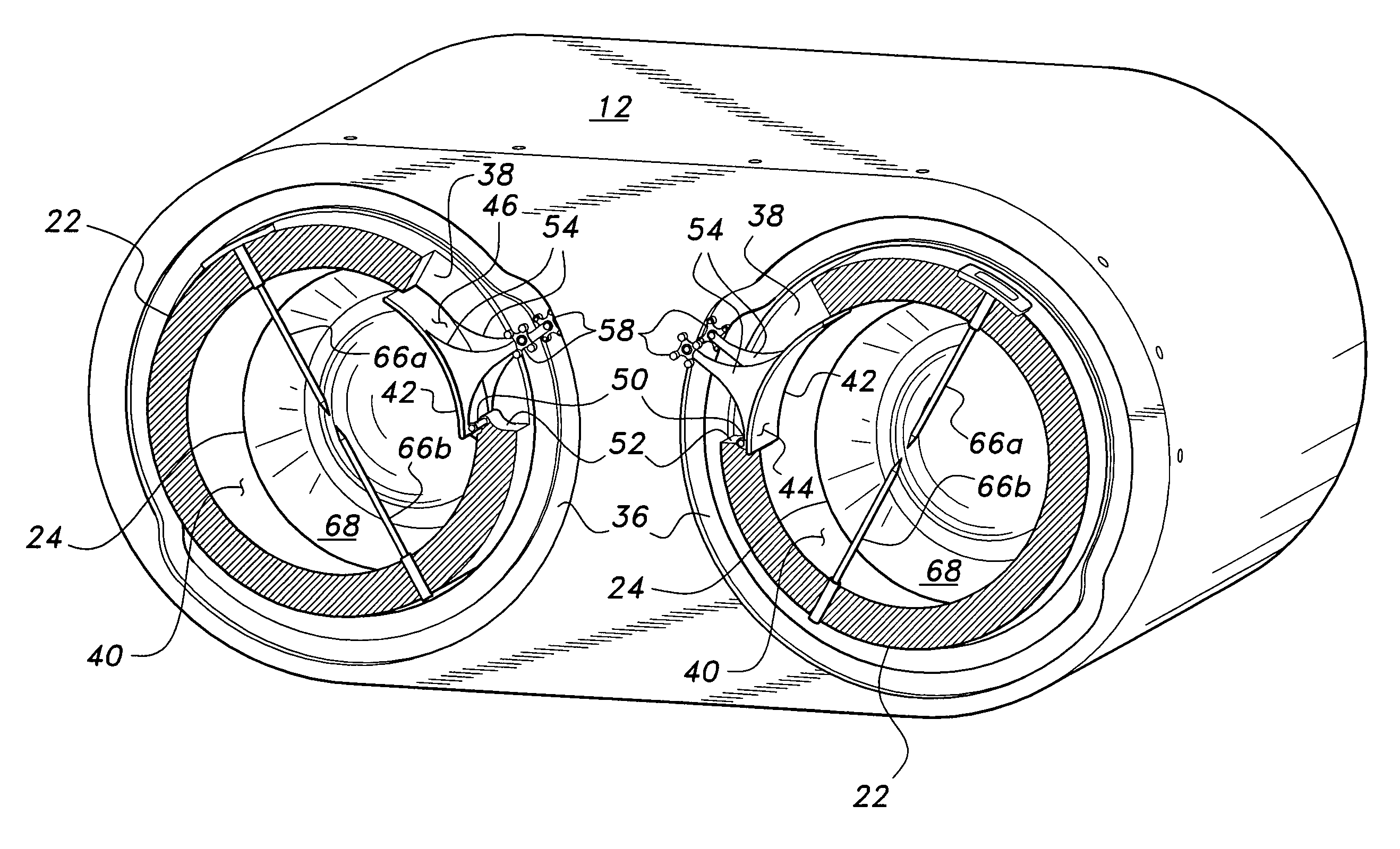
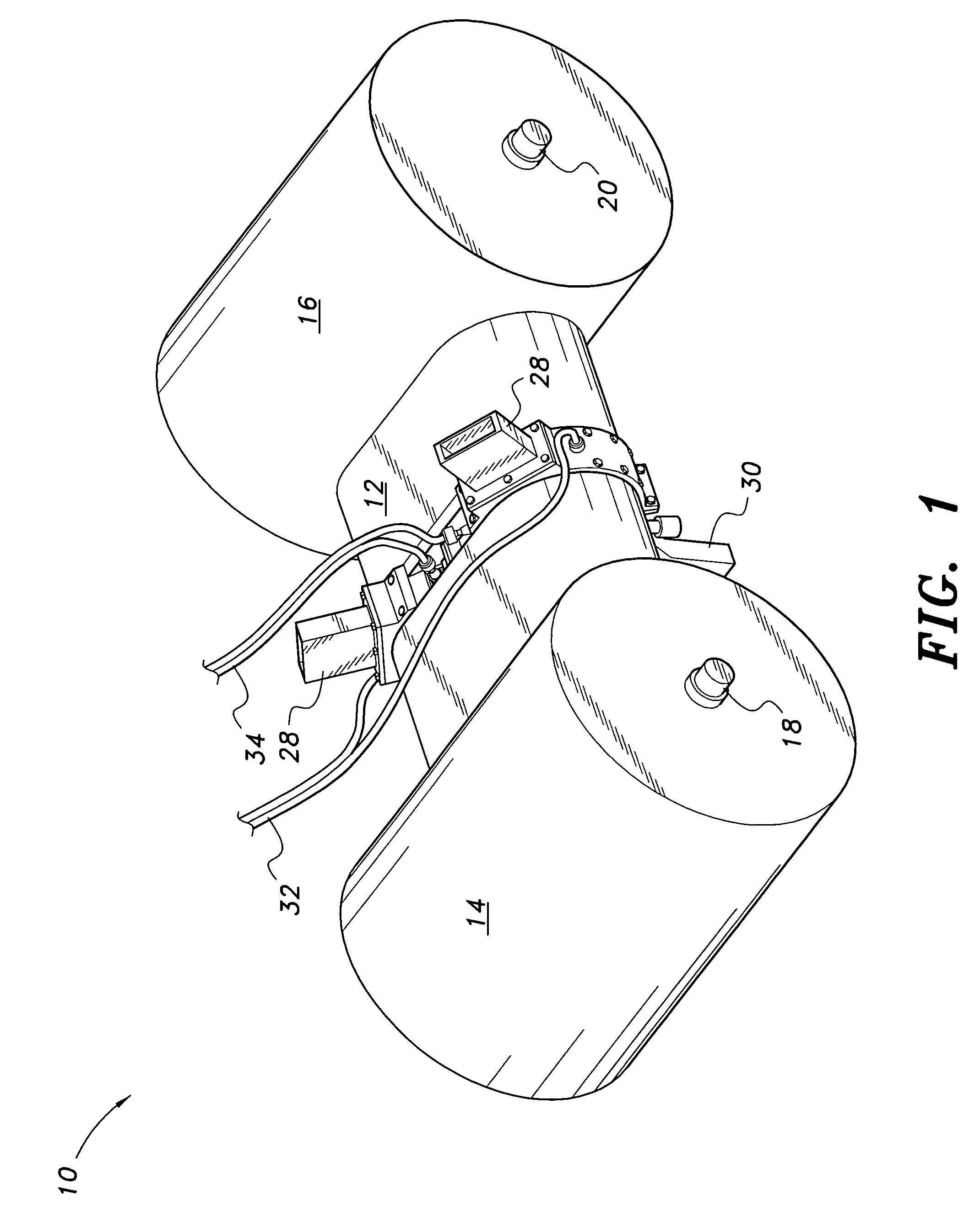
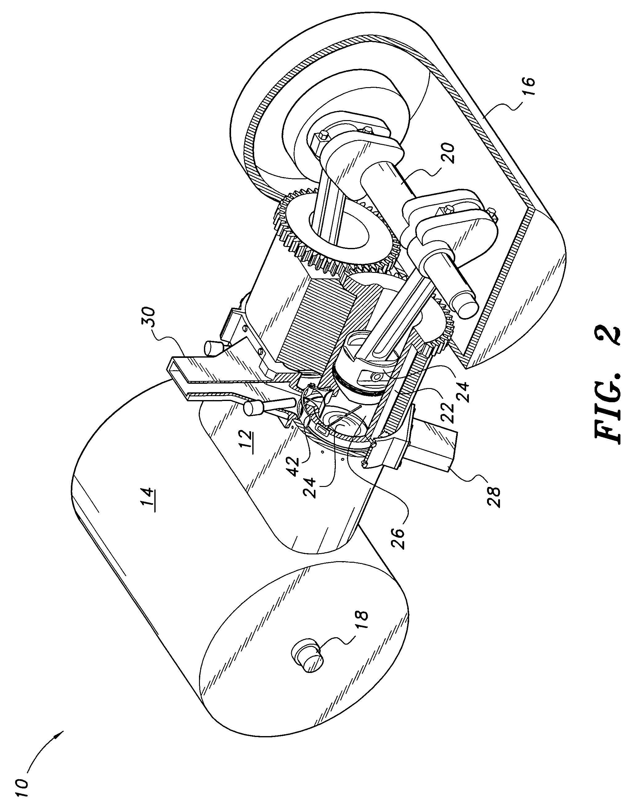
[0017]The present invention is a poppet valve mechanism configured for use with an opposed piston internal combustion engine, i.e. an engine having a single central combustion chamber between the opposed pistons of each piston pair, with each piston of the piston pair driving a separate crankshaft. A single valve port is provided medially in the single cylinder of each piston pair, i.e., at the combustion chamber defined by the cylinder and its two opposed pistons, with the cylinder rotating to align the valve port periodically with a separate intake and exhaust passage through the stationary case of the engine. The valve mechanism of the present invention periodically opens and closes the hinged poppet valve in the valve port of the cylinder as the valve port aligns with the intake and exhaust passages of the engine case, to allow the fuel and air mixture (or air only, if direct fuel injection is provided) to enter the combustion chamber and exhaust gases to be expelled from the co...


PUM


Abstract

The valve system for opposed piston engines essentially comprises a single poppet valve opening into the common combustion chamber between the two opposed pistons of each piston and cylinder pair. The engine for which the mechanism is adapted includes a rotating internal cylinder surrounding each piston pair, with a stationary outer cylinder or case surrounding the rotating cylinder. The valve is pivotally attached at one side or end thereof to the edge of the valve port of the rotating cylinder, and is actuated by an arm or arms having guides (rollers, etc.) at the distal end(s) thereof, which are captured in corresponding cam track(s) or channel(s) formed in the fixed outer cylinder or case of the engine. The cam track has a variable radius, with the valve arm(s) and guide(s) alternately lifting and lowering as the guide(s) travel(s) in the variable radius cam track(s), thereby closing and opening the valve.

Description

BACKGROUND OF THE INVENTION[0001]1. Field of the Invention[0002]The present invention relates generally to reciprocating internal combustion engines. More specifically, the present invention is a poppet valve system for an opposed piston engine configuration, in which each piston pair shares a common combustion chamber and operates two mutually opposed crankshafts.[0003]2. Description of the Related Art[0004]The concept of the opposed piston engine, i.e., an engine configuration in which the two pistons of each piston pair drive mutually opposed crankshafts disposed to the outboard sides of the engine with the two pistons having facing crowns defining a single combustion chamber therebetween, has been known for some time. A problem with such engines is the provision of suitable valving for the introduction of intake charges and the disposal of the exhaust gases from the combustion chamber. As this type of engine has no cylinder head per se, it is not possible to place poppet type va...

Claims


Application Information

Patent Timeline
Patent Type & Authority Patents(United States)
IPC IPC(8): F01B7/12F01L1/00F02N3/00
CPCF01B7/14F01L1/08F01L1/30F01L3/20F01L5/02F01L5/12F01L5/24F02B75/28
Inventor WARREN, JAMES C.
Owner ENGINUITY POWER SYST INC
Why Eureka
Try Eureka