Power transmission belt

a transmission belt and power technology, applied in the field of power transmission belts, can solve the problem of not yielding a belt with acceptable performance properties

Inactive Publication Date: 2010-08-24
CONTITECH USA INC
View PDF14 Cites 5 Cited by
  • Summary
  • Abstract
  • Description
  • Claims
  • Application Information

AI Technical Summary

Problems solved by technology

However, due to the distinct physical properties of the PBO yarns, simple substitution of PBO yarns for known polyester or aramid cords in power transmission belts may not yield a belt having acceptable performance properties.

Method used


Image

  • Power transmission belt
  • Power transmission belt
  • Power transmission belt

Examples


Embodiment Construction

[0012]The following language is of the best presently contemplated mode or modes of carrying out the invention. This description is made for the purpose of illustrating the general principles of the invention and should not be taken in a limiting sense. The scope of the invention is best determined by reference to the appended claims.

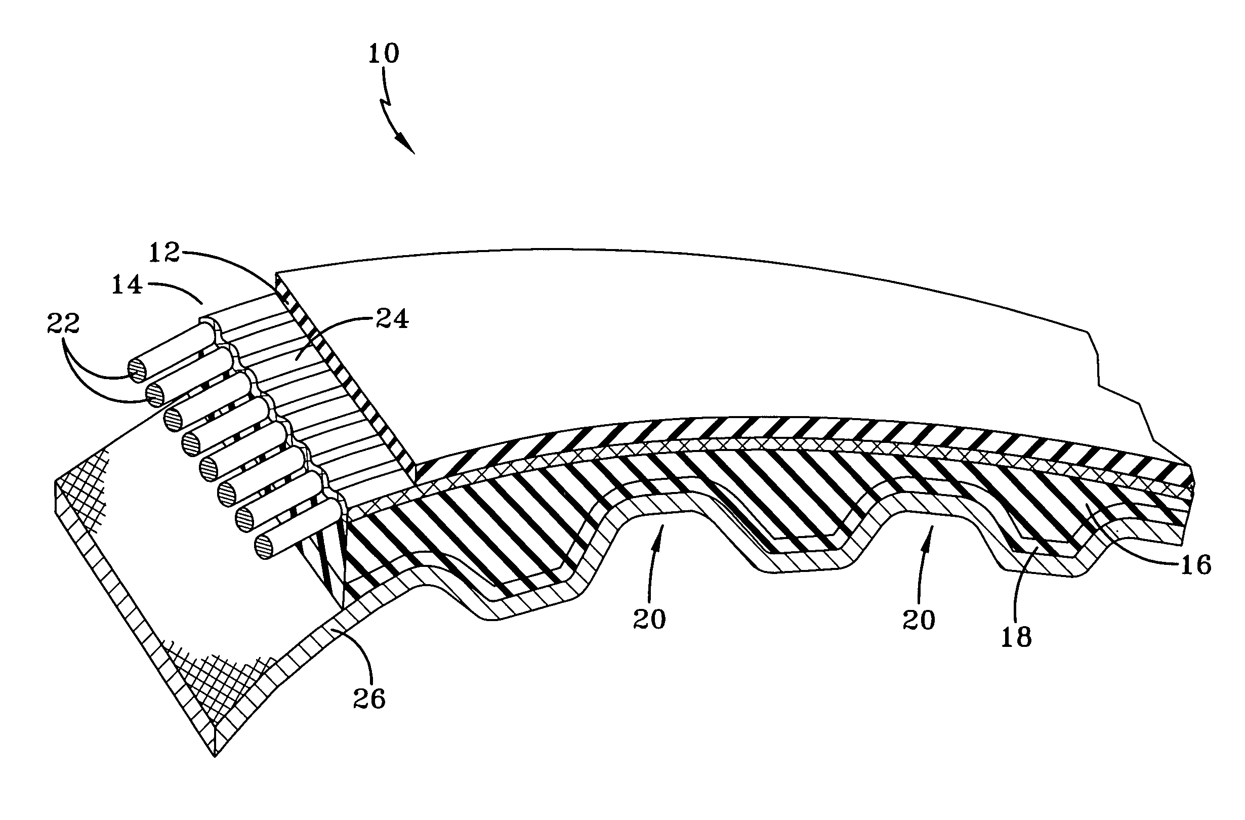
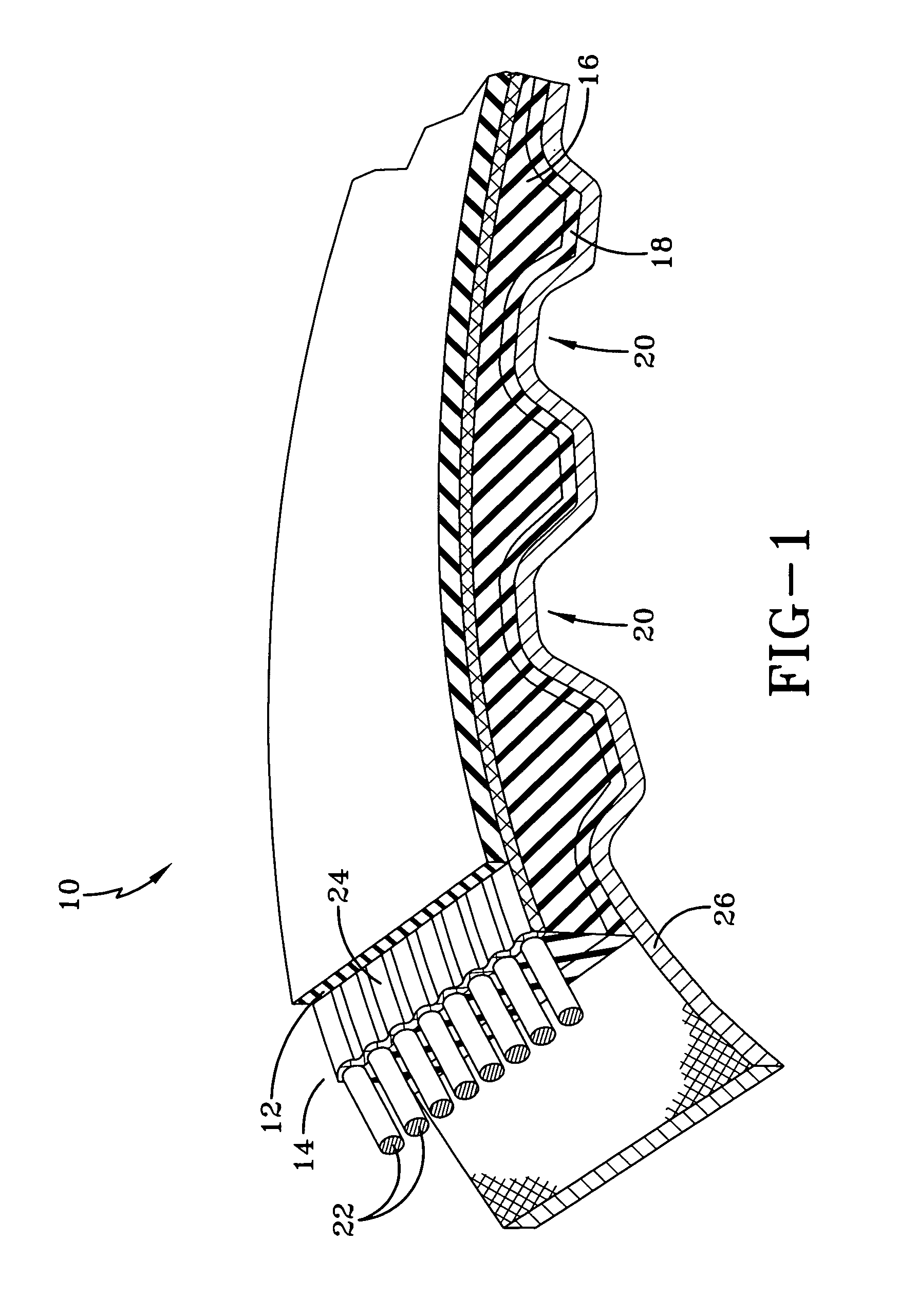
[0013]The timing belt shown generally at 10 in FIG. 1, has a tension section 12, a load carrying section 14, and a compression section 16. The compression section has a plurality of transverse ribs 18 with a plurality of transverse grooves 20. The load carrying section 14 has longitudinal reinforcing cords 22 embedded in a suitable material 24.

[0014]The tension section 12 of the belt is formed from elastomeric materials. The elastomers may be any one of those known to be suitable for use in such belts, e.g., polychloroprene, polyurethane, NBR, IIR, IR, SBR, CSM, EPDM, other thermosets, thermoplastic elastomers and other polymer alloys.

[0015]The compress...


PUM

PropertyMeasurementUnit
angleaaaaaaaaaa
tensionaaaaaaaaaa
tensile strengthaaaaaaaaaa

Abstract

A power transmission belt has a compression section, a tension section, and a load carrying section. The load carrying section has a plurality of reinforcing cords. The reinforcing cords are formed from poly(p-phenylene-2,6-benzobisoxazole) (PBO). In each reinforcing cord, the cords have a yarn twist greater than the cord twist, and the cord twist is in the range of one-forth to one-half of a ply twist.

Description

FIELD OF THE INVENTION[0001]The present invention is related to a power transmission belt. More specifically, the present invention is directed to a power transmission belt wherein the belt is reinforced with PBO fibers.BACKGROUND OF THE INVENTION[0002]In conventional power transmission belts, the belt has an inner compression section, an outer tension section, and an intermediate neutral plane. Typically, helically wound reinforcing cords are located within the neutral plane and so the neutral plane is also referred to as the load carrying zone. Such belts also having a variety of groove and rib configurations, using longitudinal or transverse grooves or a combination of both. The grooves are located in the inner compression section of the belt. The grooves assist in engaging a pulley in the power transmission system. For some belts, grooves and rib configurations may also be provided in the outer tension section.[0003]The reinforcing cords in the load carrying zone provide a major...

Claims


Application Information

Patent Timeline
Patent Type & Authority Patents(United States)
IPC IPC(8): F16G1/00F16G5/00
CPCF16G1/10F16G1/28F16G5/08D02G3/447F16G5/20Y10T428/2991Y10T428/2913Y10T428/249921
Inventor LOFGREN, JEFFREY DWIGHTGOETTSCH, LARRY DEAN
Owner CONTITECH USA INC
Why Eureka
Try Eureka