
Method and apparatus for resonant frequency identification through out-of-plane displacement detection

a technology of displacement detection and resonance frequency, applied in the field of resonance frequency identification, can solve the problems of inability to perform full-field measurement, inability to achieve full-field measurement, and inability to achieve real-time full-field measurement of the surface profile of an object in vibrating mod

Active Publication Date: 2010-08-24
IND TECH RES INST +1
View PDF9 Cites 4 Cited by
  • Summary
  • Abstract
  • Description
  • Claims
  • Application Information

AI Technical Summary

Problems solved by technology

Two-dimensional measurement of objects in vibration requires laser scanning point by point, which is more time-consuming and easily affected by environmental factors.
Therefore, there measures may hardly obtain real-time full-field measurement of the surface profile of an object in vibrating mode.
However, the above-mentioned technology cannot perform full-field measurement, and the measurements obtained by Polytec contain no phase information.
According to the above, current systems and available technologies may have the following issues.(1) Laser beams may cause damage to micro-devices under test due to overheating;(2) The time-averaging approach may require manual identification of the resonant frequency;(3) The laser source is relatively expensive and installation thereof is complicated, making it unsuitable for general MEMS / MOEMS systems.
However, during stroboscopic flashing, the displacement of the object under test has to be smaller than 1 / 20 of the wavelength of the light source; otherwise, fringes of the interference images may become blurred.

Method used


Image

  • Method and apparatus for resonant frequency identification through out-of-plane displacement detection
  • Method and apparatus for resonant frequency identification through out-of-plane displacement detection
  • Method and apparatus for resonant frequency identification through out-of-plane displacement detection

Examples


Embodiment Construction

[0029]The present invention can be exemplified by the preferred embodiment as described hereinafter.

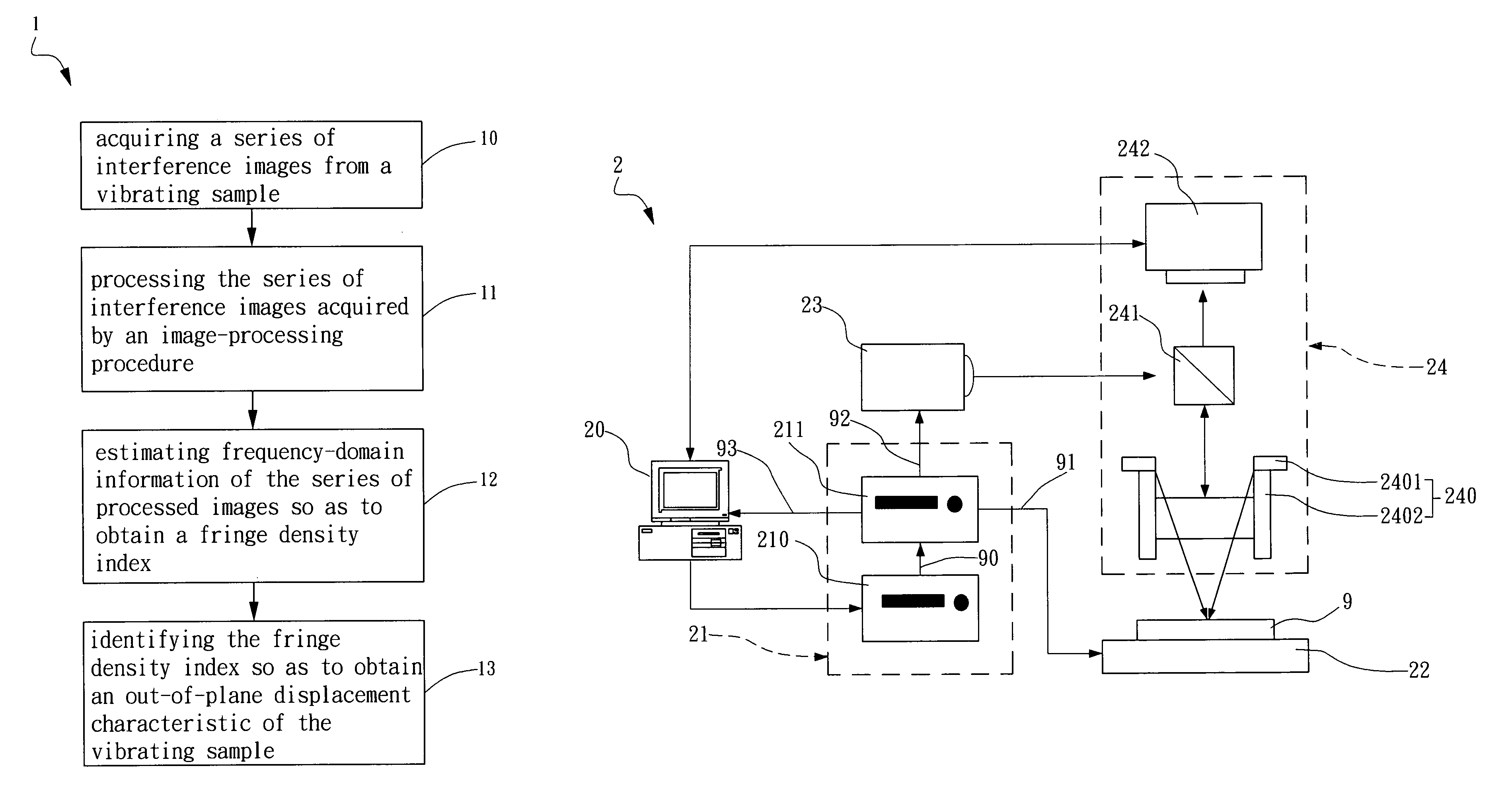
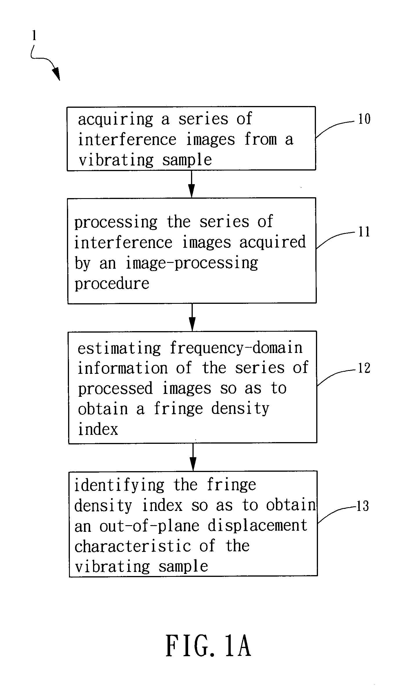
[0030]Refer to FIG. 1A, which is a flow-chart showing a method for out-of-plane displacement detection according to one embodiment of the present invention. The method comprises steps described hereinafter. First, in Step 10, a series of interference images are acquired from a vibrating sample. The vibrating sample can be a micro-mechanical structure or device, such as a cantilever and a probe of an atomic force microscopy (AFM). However, the present invention is not limited thereto. Then, in Step 11, the series of interference images acquired are processed by an image-processing procedure.

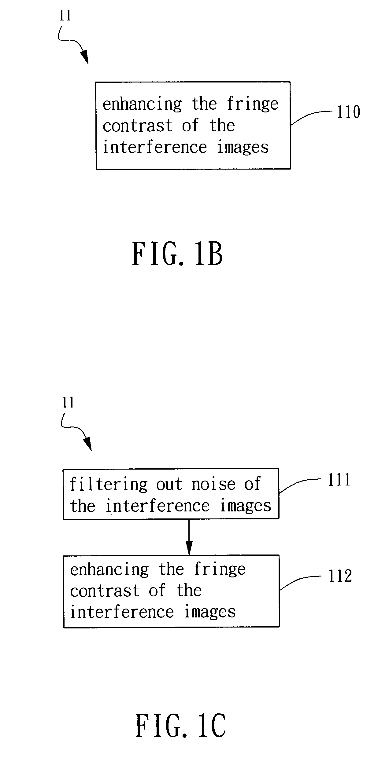
[0031]Refer to FIG. 1B, which is a flow-chart showing an image-processing procedure for out-of-plane displacement detection according to the present invention. The image-processing procedure involves a noise-filtering algorithm. In Step 110, the interference images are normalized. In general, the gr...


PUM


Abstract

A method for out-of-plane displacement detection is disclosed. The out-of-plane displacement is detected by analyzing all the fringe density indexes calculated using the frequency-domain information extracted from a series of interference images of the sample vibrating at different frequencies. The present invention further discloses a method and an apparatus for resonant frequency identification by detecting the peak value of all the fringe indexes calculated at different scanning frequencies. With the identified resonant frequency, the full-field vibratory surface profile of the sample in various resonance modes can be reconstructed.

Description

BACKGROUND OF THE INVENTION[0001]The present invention generally relates to resonant frequency identification, especially for resonant frequency identification through out-of-plane displacement detection.[0002]The conventional optical interferometric surface profilometer has been developed mainly for static measurement of nano-scale three-dimensional surface profiles. It has been widely employed for measuring surface roughness and uniformity on semiconductor wafer, depth of laser mark, metal-bump size and co-planarity during flip chip bonding, size and height of spacers in liquid-crystal display panels, and surface profile of fiber end-face and micro optical devices. In recent years, vibratory measurement has been incorporated into the optical interferometric surface profilometer, thus widening its applications in observing and measuring the vibratory behavior of functional elements and thin-films in micro-electro-mechanical system (MEMS) and micro-opto-electro-mechanical system (MO...

Claims


Application Information

Patent Timeline
Patent Type & Authority Patents(United States)
IPC IPC(8): G01B9/02
CPCG01B11/161
Inventor CHEN, LIANG-CHIACHANG, CHUNG-CHUHUANG, YAO-TINGCHEN, JIN-LIANG
Owner IND TECH RES INST
Learn More