Airflow estimation method and apparatus for internal combustion engine

a technology for internal combustion engines and airflow estimation, which is applied in the direction of combustion-air/fuel-air treatment, electric control, instruments, etc., can solve the problems of substantial noise, engine operating in hcci mode is also affected by maf signals which can be substantially noisy, and maf signals can similarly be substantially noisy, so as to accurately estimate the mass airflow

Inactive Publication Date: 2010-08-24
GM GLOBAL TECH OPERATIONS LLC
View PDF7 Cites 24 Cited by
  • Summary
  • Abstract
  • Description
  • Claims
  • Application Information

AI Technical Summary

Benefits of technology

[0006]In the present invention, model-based estimation and control methodology based on MAF measurement is developed to accurately estimate mass airflow without introducing time delay for robust transient operations.
[0007]A method for unfiltered intake airflow determination in a substantially unthrottled internal combustion engine includes modeling intake airflow using a low-order differential equation. The low-order differential equation includes an estimated airflow term and a desired airflow term, wherein the actual airflow follows the desired airflow as described by the low-order differential equation. The low-order differential equation is tuned in accordance with adaptive parameters operative on the estimated airflow term and the desired airflow term. The tuning minimizes error between the estimated airflow term and the actual airflow.

Problems solved by technology

However, during minimally throttled operation, noise levels can be substantial due to significant coupling of intake dynamics of the cylinders with the intake manifold and MAF sensor.
Therefore, engines operating in an HCCI mode are also affected by MAF signals which can be substantially noisy.
Similarly, in diesel engines, which operate without air throttling, MAF signals can similarly be substantially noisy.
Although the high-frequency components in the MAF measurement can be reduced using a low pass filter, a filtered signal produces an undesirable time delay in the MAF measurement.
Adapting fuel injection command using a filtered, and hence time delayed, MAF measurement can cause significant air-fuel ratio deviations during engine transient operations resulting in undesirable combustion results including, for example, partial burn, misfires, excessive emissions, combustion phase shifts, etc.

Method used


Image

  • Airflow estimation method and apparatus for internal combustion engine
  • Airflow estimation method and apparatus for internal combustion engine
  • Airflow estimation method and apparatus for internal combustion engine

Examples


Embodiment Construction

[0014]The present invention will now be described with respect to a HCCI engine. However, the invention is fully applicable to other engine types, including conventionally throttled spark-ignited engines, diesel cycle engines, or any variety of engines employing measured mass airflow.

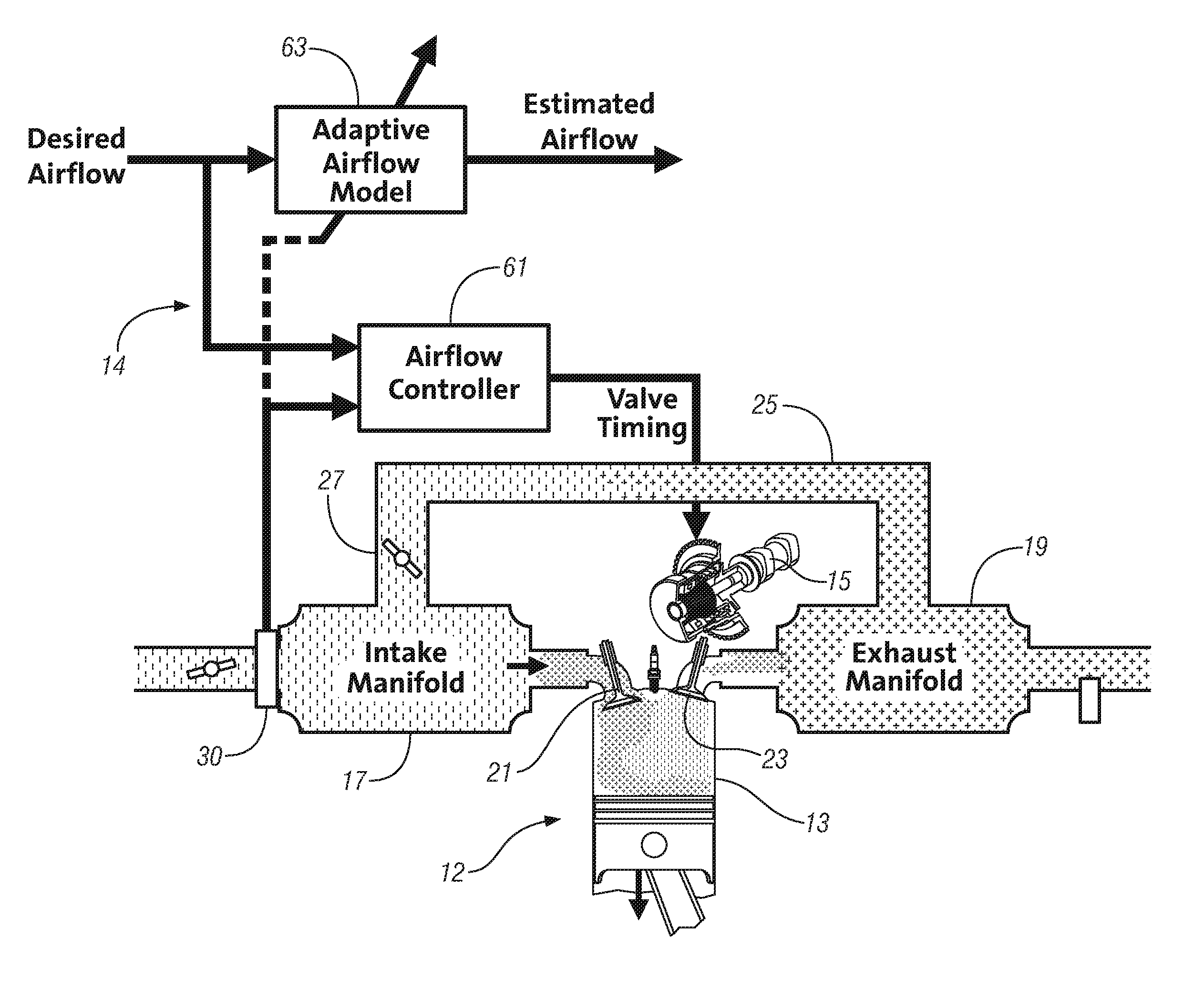
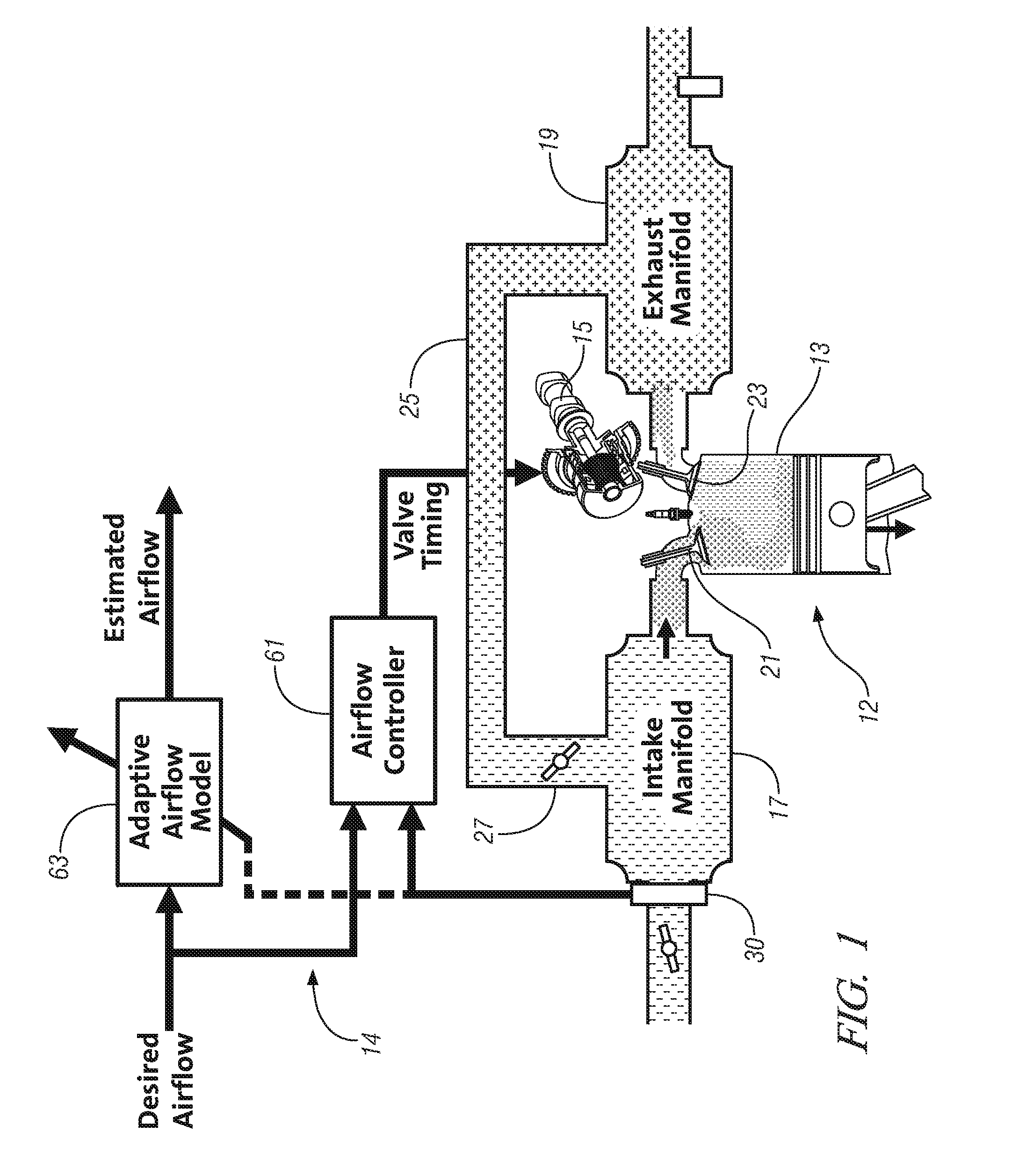
[0015]Referring now to FIG. 1, illustrated is a block diagram showing an engine 12 capable of operating with homogeneous charge compression ignition (HCCI) and a combustion control system 14 and method for controlling combustion in the engine.

[0016]The engine 12 may include various features or devices, including power producing combustion chambers 13 connected with an intake air system 17 and an exhaust system 19, intake 21 and exhaust 23 valves with some form of variable valve actuation system 15 operative to control intake flow to and exhaust flow from the combustion chambers, an external exhaust recirculation system 25 including an EGR valve 27 connected between the intake and exhaust systems, and fu...


PUM


Abstract

A model-based estimation of mass airflow is provided which provides an accurate estimation of mass airflow without introducing undesirable time delays characteristic of filtered mass airflow signals.

Description

CROSS REFERENCE TO RELATED APPLICATIONS[0001]This application claims the benefit of U.S. Provisional Application No. 60 / 794,580 filed on Apr. 24, 2006 which is hereby incorporated herein by reference.TECHNICAL FIELD[0002]This invention relates to internal combustion engines. More particularly, the invention is concerned with accurately estimating mass airflow to the engine.BACKGROUND OF THE INVENTION[0003]The combustion process of homogeneous charge compression ignition (HCCI) engines depends strongly on factors such as cylinder charge composition, temperature, and pressure at the intake valve closing. Hence, the control inputs to the engine, for example, fuel injection mass and timing and intake / exhaust valve profile, must be carefully coordinated to ensure robust auto-ignition combustion. Generally, for best fuel economy, an HCCI engine operates un-throttled and with a lean air-fuel mixture. Further, in an HCCI engine using an exhaust recompression valve strategy, the cylinder cha...

Claims


Application Information

Patent Timeline
Patent Type & Authority Patents(United States)
IPC IPC(8): B60T7/12
CPCF02D13/0219F02D41/0002F02D41/1402F02D41/18F02M25/0752F02B1/12F02D13/0253F02D13/0265F02D41/3035F02D2041/001F02D2200/0402F02M25/0715Y02T10/42Y02T10/18F02M26/01F02M26/13Y02T10/12Y02T10/40
Inventor KANG, JUN-MOCHANG, CHEN-FANGCHEN, JYH-SHINKUO, TANG-WEI
Owner GM GLOBAL TECH OPERATIONS LLC
Why Eureka
Try Eureka