Lawn mower blade assembly having blade mount for quick blade replacement and associated methods

a technology of blade assembly and blade mount, which is applied in the direction of mowers, agriculture tools and machines, agriculture, etc., can solve the problems of cutting blades subjected to potentially damaging operating conditions, cutting blades wear and become dull, and losing their ability to effectively cut grass

Inactive Publication Date: 2010-08-31
BEVER CHRISTOPHER
View PDF34 Cites 28 Cited by
  • Summary
  • Abstract
  • Description
  • Claims
  • Application Information

AI Technical Summary

Benefits of technology

[0009]In view of the foregoing background, it is therefore an object of the present invention to provide a lawn mower blade assembly that facilitates cutting blade removal and sharpening, or replacement.
[0011]Accordingly, a simple tap with a hammer on the at least one sliding retainer can secure the cutting blade and blade mount together. Centrifugal force maintains tight the engagement between the at least one wedge surface of the blade mount and the at least one sliding retainer, making the coupling between the blade mount and the cutting blade particularly secure.
[0012]The cutting blade and / or the blade mount may have at least one release notch therein. The at least one sliding retainer, when in the released position, may be aligned with the at least one release notch to permit removal of the cutting blade from the blade mount. In other words, a simple tap with the hammer on the at least one sliding retainer in the reverse direction frees the sliding retainer to be moved in alignment with the release notch. Thus, this lawn mower blade assembly provides for quick and simple cutting blade removal and sharpening, or replacement, saving homeowners and lawn service providers time and money.
[0018]Another aspect is directed to a method for removably coupling a cutting blade to a lawn mower. The method may comprise securing a blade mount having at least one wedge surface thereon to a rotatable driveshaft of the lawn mower. The cutting blade may be positioned adjacent the blade mount. At least one sliding retainer may be slidably moved from a released position to a locked position and with the at least one sliding retainer having at least one wedge surface thereon cooperating with the at least one wedge surface of the blade mount to securely couple the cutting blade to the blade mount when in the locked position.

Problems solved by technology

The cutting blade is subjected to potentially damaging operating conditions, often contacting sticks, rocks, tree roots, and other debris.
Cutting blades wear and become dull over time, losing their ability to effectively cut grass.
To replace a conventional cutting blade, an individual typically removes the fastener coupling the lawn mower blade to the rotatable driveshaft, which may be time consuming and difficult to accomplish.
The removal and sharpening, or complete replacement of such cutting blades is particularly burdensome for lawn service providers who use fleets of such lawn mowers and cut large amounts of grass on a daily basis.
These prior approaches, however, may not facilitate cutting blade removal and sharpening, or replacement as easily and quickly as some users may desire.

Method used


Image

  • Lawn mower blade assembly having blade mount for quick blade replacement and associated methods
  • Lawn mower blade assembly having blade mount for quick blade replacement and associated methods
  • Lawn mower blade assembly having blade mount for quick blade replacement and associated methods

Examples


Embodiment Construction

[0039]The present invention will now be described more fully hereinafter with reference to the accompanying drawings, in which preferred embodiments of the invention are shown. This invention may, however, be embodied in many different forms and should not be construed as limited to the embodiments set forth herein. Rather, these embodiments are provided so that this disclosure will be thorough and complete, and will fully convey the scope of the invention to those skilled in the art. Like numbers refer to like elements throughout.

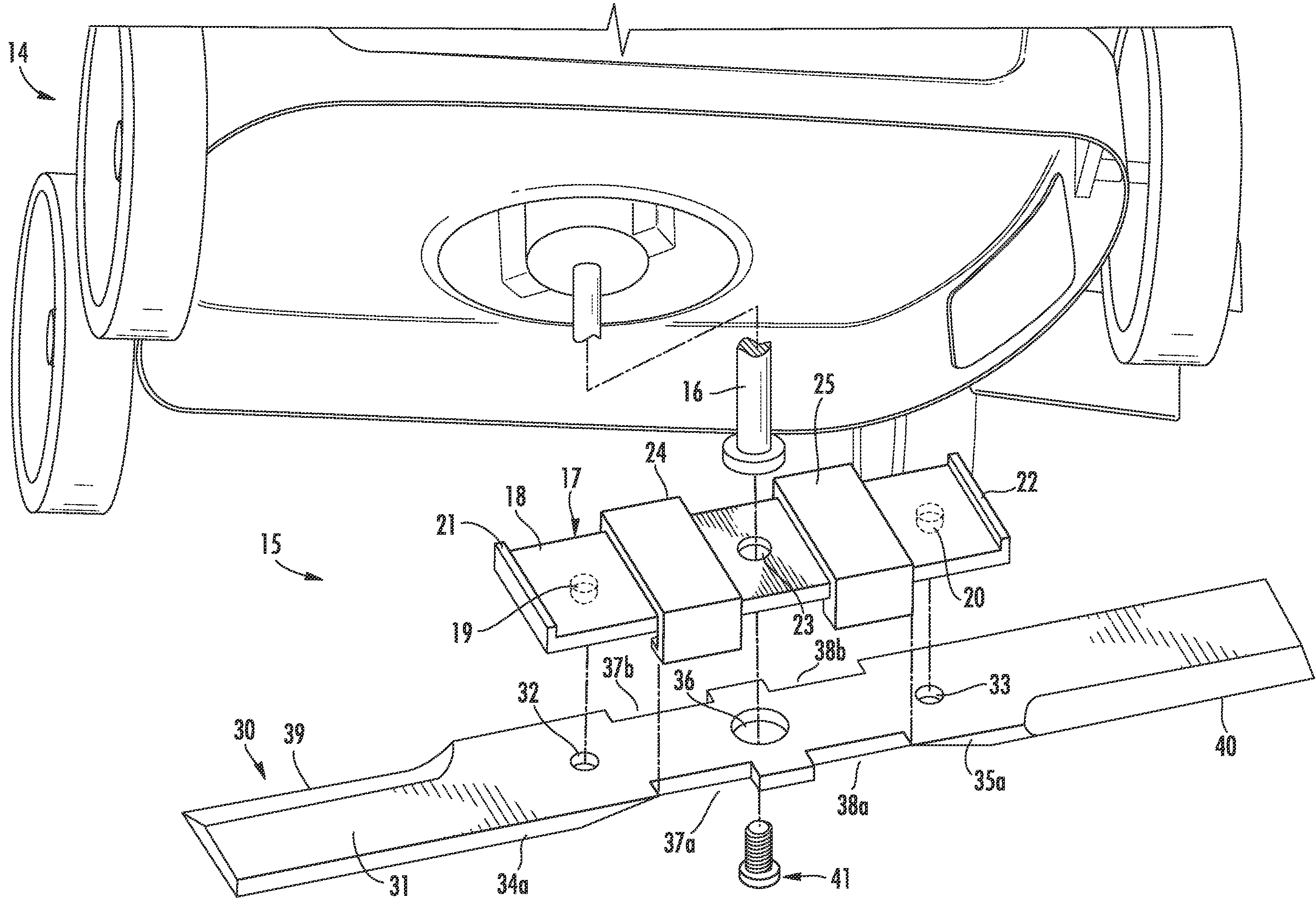
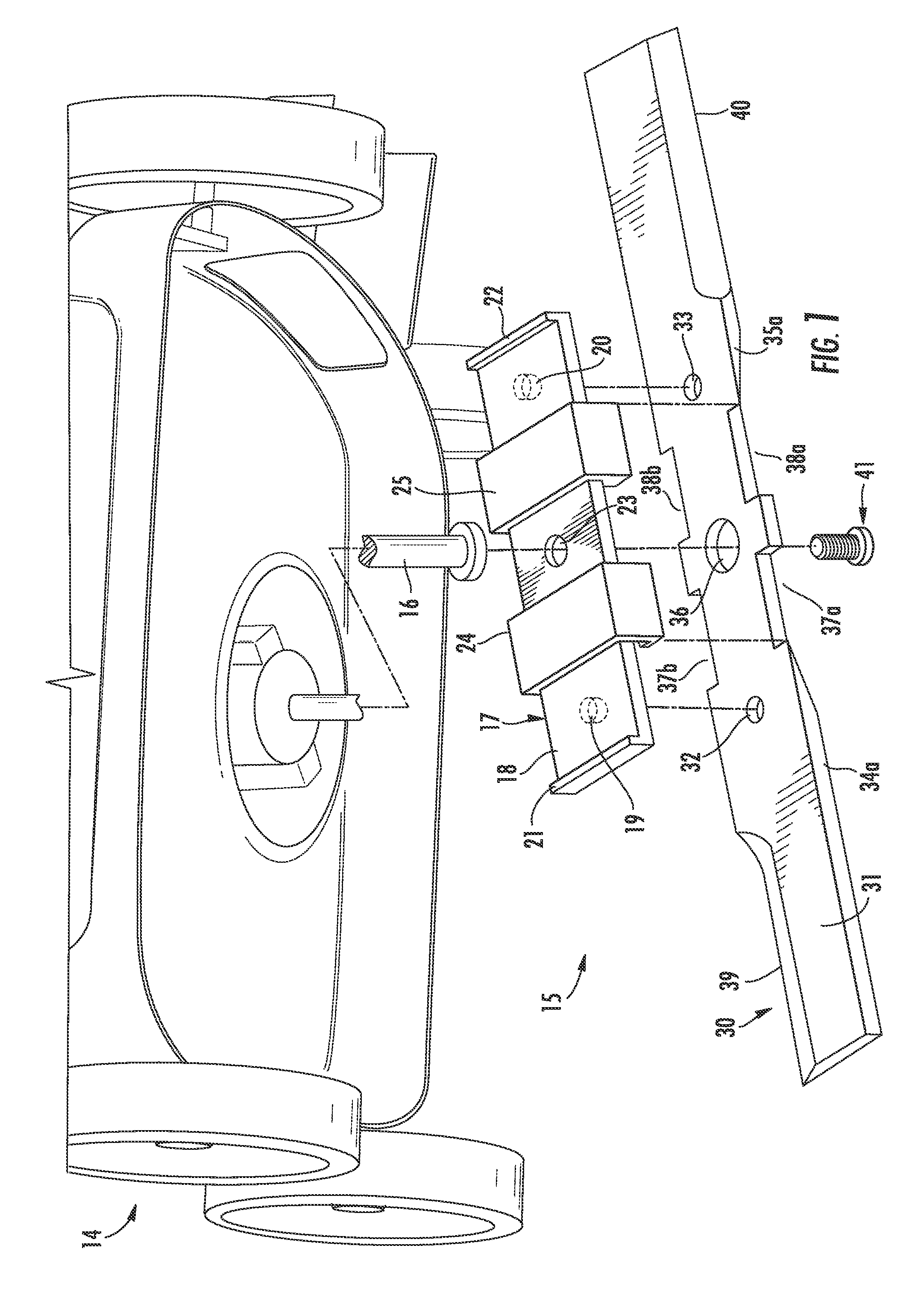
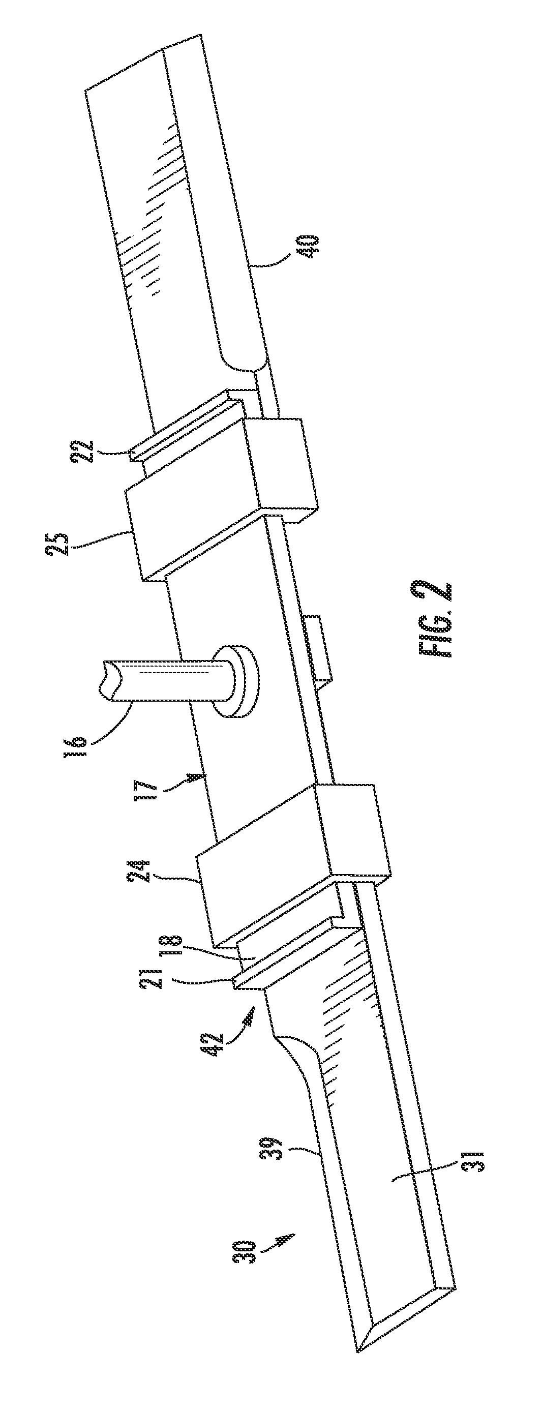
[0040]Referring initially to FIGS. 1-8, a first embodiment of a lawn mower blade assembly 15 for a rotatable driveshaft 16 of a lawn mower 14 is now described. The lawn mower blade assembly 15 comprises a blade mount 17 to be secured to the rotatable driveshaft 16. A cutting blade 30 having a pair of cutting edges 39, 40 on opposite sides and adjacent opposite ends of the cutting blade is removably coupled to the blade mount 17 and defines therewith a blad...


PUM


Abstract

A lawn mower blade assembly for a rotatable driveshaft includes a blade mount to be secured to the rotatable driveshaft and having at least one wedge surface thereon. A cutting blade is removably coupled to the blade mount. At least one sliding retainer removably couples the cutting blade to the blade mount and is slidably movable between a locked position and a released position. The at least one sliding retainer has at least one wedge surface thereon cooperating with the at least one wedge surface of the blade mount to securely couple the cutting blade to the blade mount when in the locked position.

Description

RELATED APPLICATIONS[0001]The present application is a continuation-in-part of U.S. application Ser. No. 12 / 137,911, filed on Jun. 12, 2008, the entire contents of which are incorporated herein by reference.FIELD OF THE INVENTION[0002]The present invention relates to the field of lawn mower blade assemblies, and, more particularly, to lawn mower blade assemblies that facilitate quick cutting blade replacement and related methods.BACKGROUND OF THE INVENTION[0003]Rotary lawn mowers are widely used by both homeowners and lawn service providers for cutting grass to maintain the tidy appearance of lawns located about residences and buildings. Such lawn mowers typically include an internal combustion engine or electric motor to rotate a driveshaft, and a cutting blade coupled to the driveshaft by a fastener. The cutting blade is therefore rotated, severing individual blades of grass it passes through the grass. The rotating cutting blade generates currents of air that may cause the blades...

Claims


Application Information

Patent Timeline
Patent Type & Authority Patents(United States)
IPC IPC(8): A01D34/52A01D34/73
CPCA01D34/733
Inventor BEVER, CHRISTOPHER
Owner BEVER CHRISTOPHER
Why Eureka
Try Eureka