Viscosity measurement

Active Publication Date: 2010-08-31
SCHLUMBERGER TECH CORP
View PDF27 Cites 37 Cited by
  • Summary
  • Abstract
  • Description
  • Claims
  • Application Information

AI Technical Summary

Problems solved by technology

However, the measurements only have meaning for the specific test equipment and over a narrow range of viscosities.

Method used


Image

  • Viscosity measurement
  • Viscosity measurement
  • Viscosity measurement

Examples


example

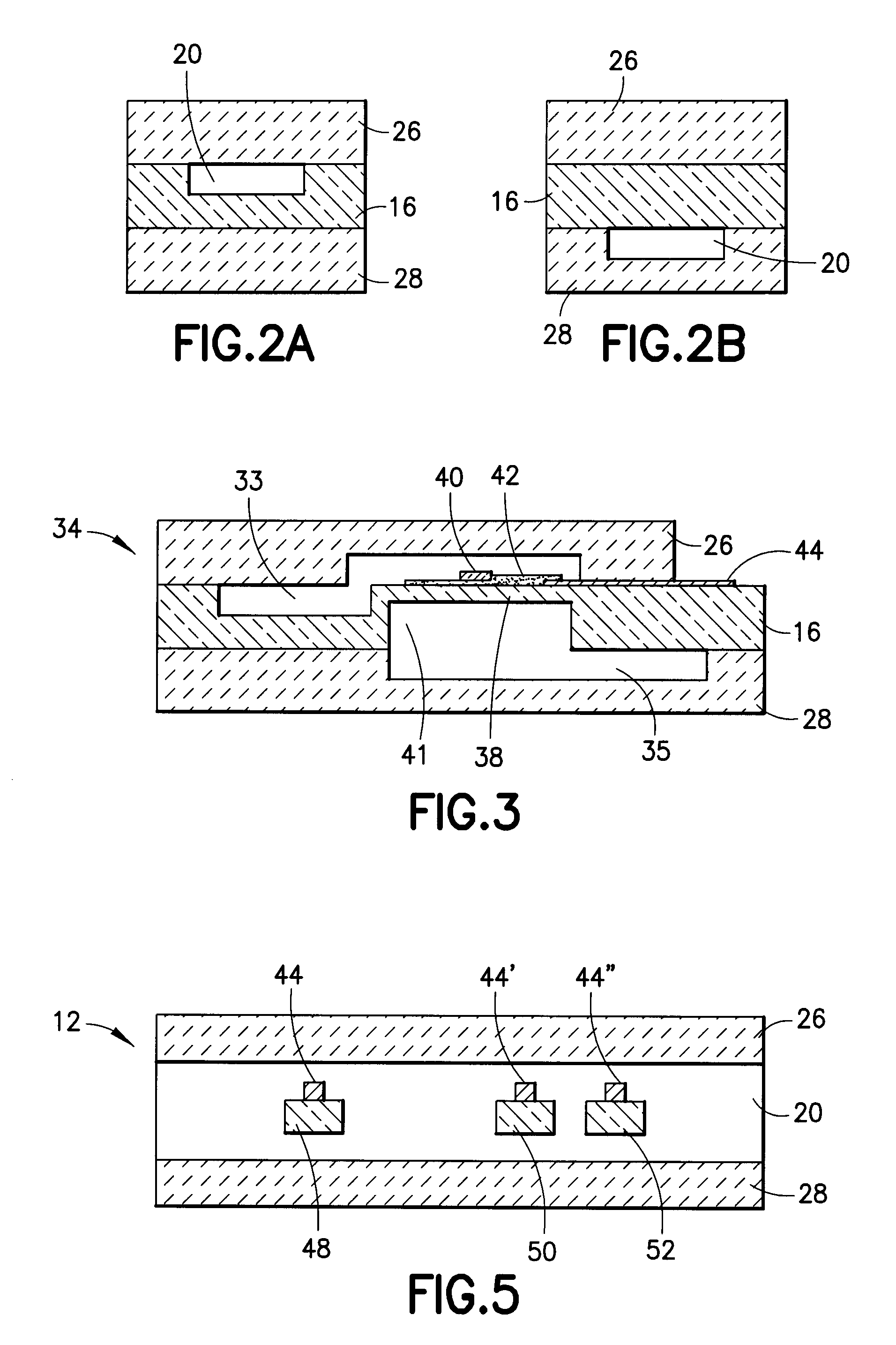
[0109]FIG. 11 graphically illustrates one embodiment of the flow rate sensor 12 of FIG. 5. A small volume of hexadecane was introduced into the flow rate sensor at a pump flow rate, in microliters per minute, determined by an external pump. Thermal pulses were generated by tracer emitter 48 and the time for the thermal pulse to reach first tracer detector 50 (represented by diamonds) and second tracer detector 52 (represented by triangles), measured as heat velocity in millimeters per second. The time for the thermal pulse to traverse the distance from the first tracer detector 50 to the second tracer detector 52 was also plotted in FIG. 9 (represented by circles) and is a straight line. This indicated that if the flow rate sensor 12 measured the heat velocity, the flow rate of a liquid may be calculated accurately. It was therefore not necessary to know a-priori the flow rate of a test fluid demonstrating that the micro-fluidic sensors described herein are effective for down hole a...


PUM

PropertyMeasurementUnit
diameteraaaaaaaaaa
temperatureaaaaaaaaaa
rheological propertyaaaaaaaaaa

Abstract

A micro-fluidic device and methods for measuring one or more rheologic properties of a fluid. The micro-fluidic device includes a substrate and at least one cover bonded to a surface of the substrate with a fluid channel formed in at least one of the cover or the substrate. Further, the micro-fluidic device includes a first differential pressure gauge that can have a first differential pressure sensor in fluid communication with both a first pressure site and a second pressure site. Further still, the micro-fluidic device includes the first pressure site and the second pressure site that can be spaced apart by a first section of the fluid channel. Also, the micro-fluidic device includes a data processor communicatively coupled to the first differential pressure sensor, so as to receive data generated by the first differential pressure sensor.

Description

BACKGROUND OF THE INVENTION[0001]1. Field of the Invention[0002]The invention relates to a device and methods to determine rheological properties of a fluid, such as absolute viscosity. More particularly, the fluid flows through a micro-fluidic sensor, e.g., micro-fluidic device. A Micro Electro Mechanical System (MEMS) device that is a component of the micro-fluidic sensor measures a pressure drop and, optionally, a flow rate. Utilizing this data, a processor can calculate rheological properties.[0003]2. Description of the Related Art[0004]Fluid analysis is important in the oil field industry. Construction decisions for a new well are largely based on measurements of fluid properties, as performed down hole (directly on reservoir fluids) or up hole (on the surface). Information regarding the chemical composition, phase diagram, density and viscosity of the fluid are critical to deciding which zones of a particular well are economical to produce and to installing the right infrastru...

Claims


Application Information

Patent Timeline
Patent Type & Authority Patents(United States)
IPC IPC(8): G01N11/08
CPCG01N11/08
Inventor ANGELESCU, DAN E.CHEN, HUAHARRISON, CHRISTOPHERSULLIVAN, MATTHEWJUNDT, JACQUES
Owner SCHLUMBERGER TECH CORP
Why Eureka
Try Eureka