Apparatus for linear illumination of a moving product web

a technology of linear illumination and product web, which is applied in the direction of optical radiation measurement, photometry, electromagnetic radiation sensing, etc., can solve the problems of insufficient scanning of a multiplicity of product webs that require diffuse light, and achieve the effect of increasing reflectivity, reducing luminance with the number of reflections, and high reflectivity

Active Publication Date: 2010-08-31
ADVANCED VISION TECH
View PDF5 Cites 10 Cited by
  • Summary
  • Abstract
  • Description
  • Claims
  • Application Information

AI Technical Summary

Benefits of technology

[0011]The apparatus in accordance with the invention serves the purpose of linear illumination of a moving product web. It has at least one light-emitting light source, it being of no importance how the light source generates the light. For example, the light source could be a halogen lamp, a light-emitting diode, a neon tube, an incandescent lamp or a laser. This enumeration is not, however, to be understood as exhaustive. Particularly in the case of the use of modern line cameras of high pixel density for optimum scanning of the product web, very small photodiodes are used which require a very large luminance in order to attain a photosignal which can be effectively evaluated. If a line camera is used, linear illumination of the product web is sufficient in principle, since the camera can in any case evaluate only a linear region of the product web. It is advantageous in this case to illuminate the product web in as linear a fashion as possible with a small line width in order to implement the highest possible luminance on the small evaluated surface. This would be possible in principle with directed light which is focused onto the product web via appropriate optics. However, this measure has the disadvantage that it is impossible for a multiplicity of product webs that require diffuse light to be scanned adequately. Diffuse light is essential as regards printed image detection, in particular. In order to bring diffuse light with high luminance onto a linear evaluation region of the product web, it is provided according to the invention that the light emitted by the light source is reflected towards the product web by at least one tubular reflector. The light is preferably multiply reflected in the tubular reflector until it reaches a light exit slit facing the product web. This light exit slit is illuminated in this case with high luminance and can therefore also be optically scanned effectively by highly resolving cameras with a small pixel structure. For this purpose, the tubular reflector has at least one observation slit at which light reflected by the product web can exit. This observation slit lies opposite the light exit slit. A line camera can therefore be provided above the observation slit so that it looks onto the illuminated product web through the observation slit. The observation slit can in this case remain narrow so that only a little light from the light source leaves the observation slit directly. Nevertheless, the product web can be scanned in a planar fashion when it moves transverse to the observation slit. In this way, a very low light intensity of the at least one light source suffices to generate a high luminance in the region of the light exit slit. Consequently, the illumination apparatus not only becomes energy efficient, but also reduces problems with the dissipation of heat from the light source. In order to adjust the camera above the observation slit, it is sufficient to find that point at which the observed image brightness is at a maximum. Consequently, the correct adjustment of the camera in relation to the observation slit of the illumination apparatus can be attained very easily.

Problems solved by technology

However, this measure has the disadvantage that it is impossible for a multiplicity of product webs that require diffuse light to be scanned adequately.

Method used


Image

  • Apparatus for linear illumination of a moving product web
  • Apparatus for linear illumination of a moving product web
  • Apparatus for linear illumination of a moving product web

Examples


Embodiment Construction

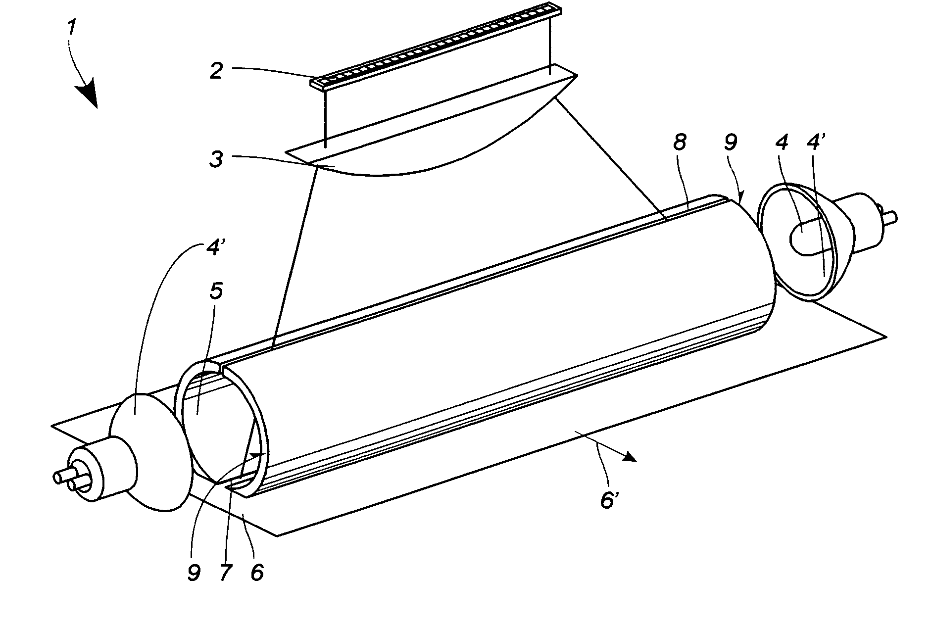
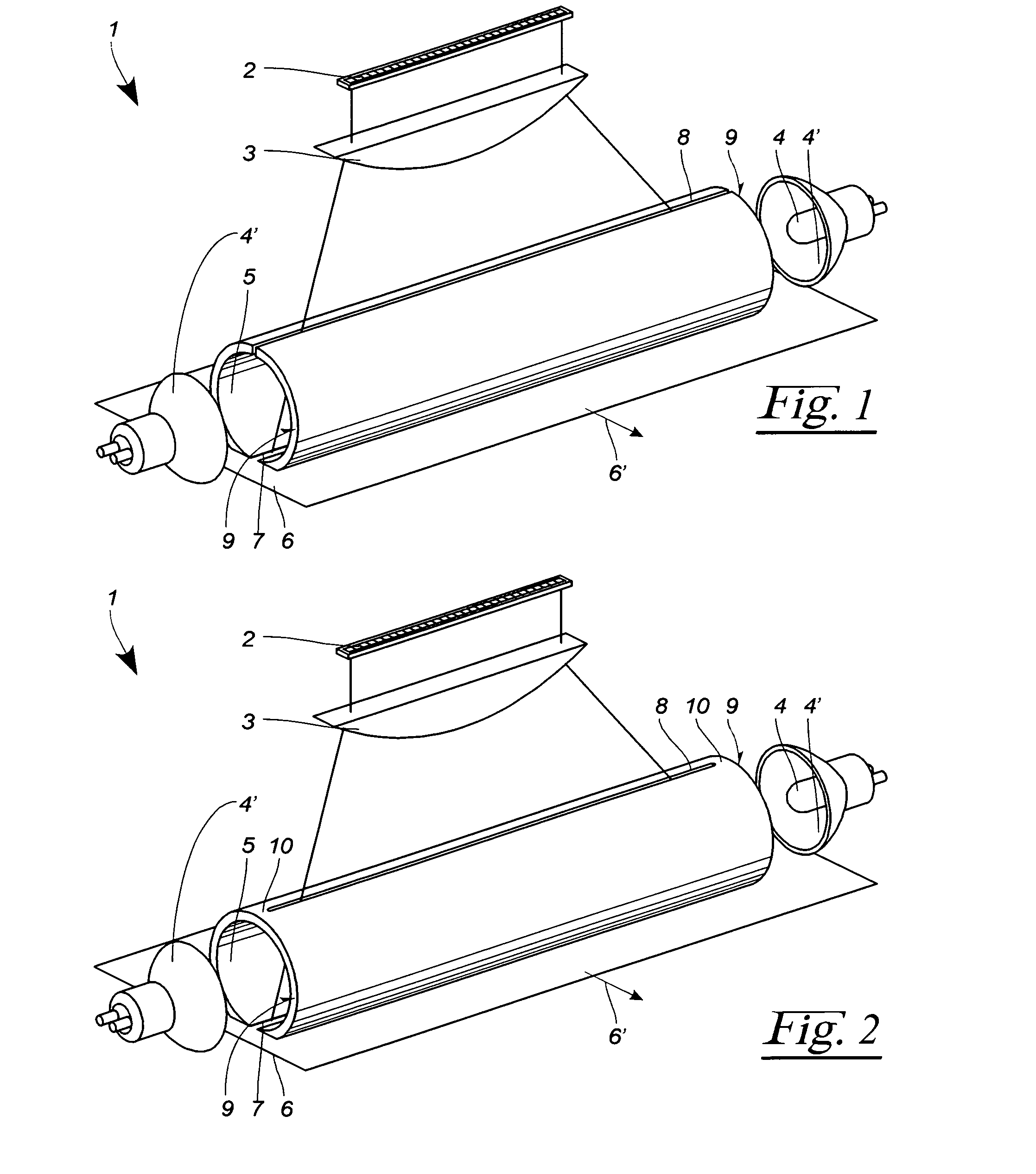
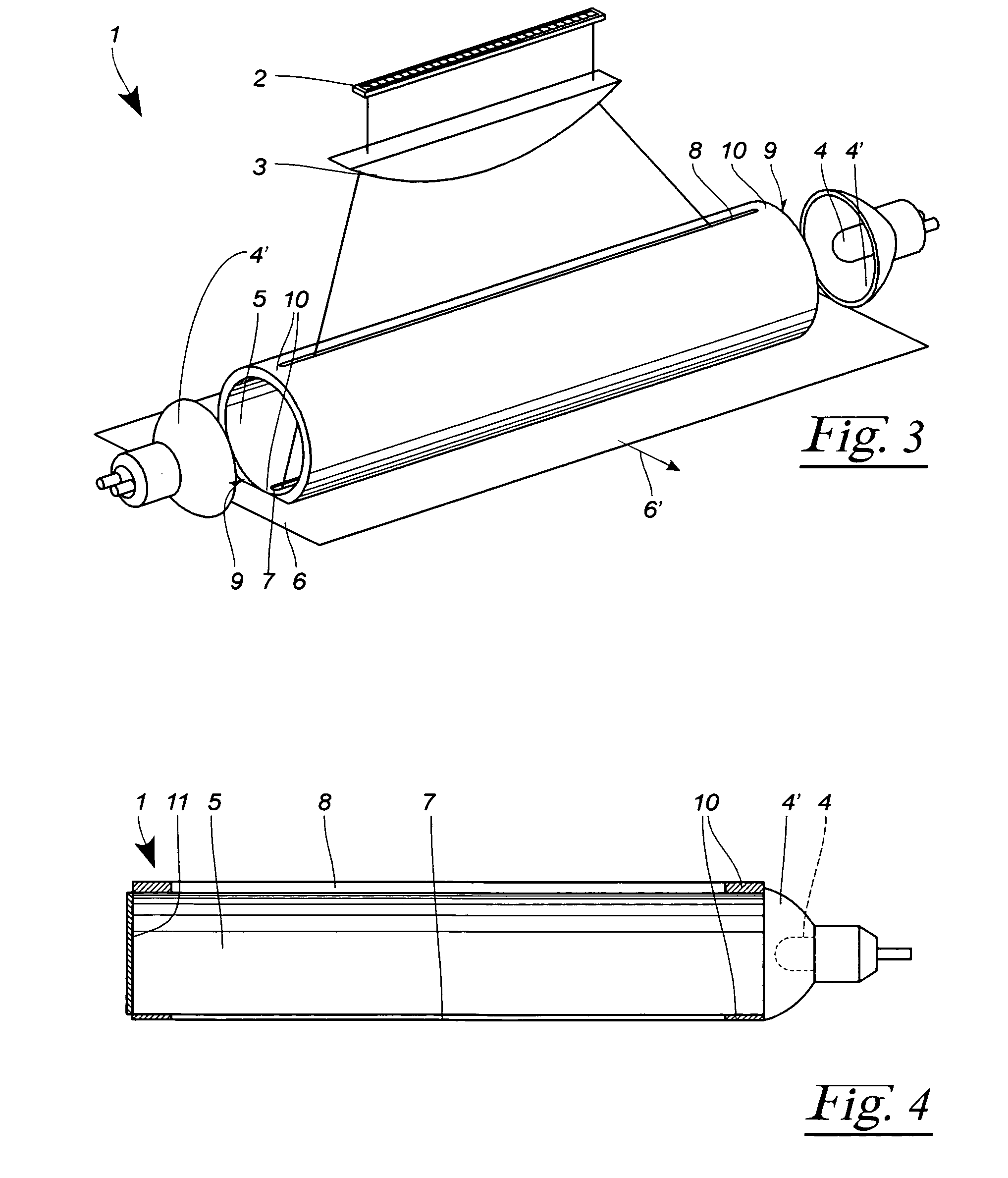
[0029]FIG. 1 shows a three-dimensional, diagrammatic exploded illustration of an illumination apparatus 1 which is assigned a line camera 2. The line camera 2 has an objective 3 in the form of a cylindrical lens which focuses the recorded image onto the line camera 2.

[0030]The illumination apparatus 1 has two light sources 4 which are provided at both end faces 9 of a tubular reflector 5. Provided around the two light sources 4 are reflectors 4′ which close the two end faces of the reflector 5.

[0031]On its side facing a product web 6 moving in the direction 6′, the tubular reflector 5 has a light exit slit 7 which completely penetrates the reflector 5. In the region of the light exit slit 7, the reflector 5 is flattened on the product web side in order to be able to guide the product web 6 more closely up to the reflector 5. Provided opposite the light exit slit 7 is an observation slit 8 which likewise completely penetrates the reflector 5. The two slits 7, 8 therefore divide the r...


PUM


Abstract

An apparatus (1) serves for linear illumination of a moving product web (6), the apparatus (1) having at least one light source (4) emitting light. In order to achieve high luminance in a linear subregion of the product web (6), at least a portion of the light emitted by the light source (4) is reflected towards the product web (6) by at least one tubular reflector (5). The tubular reflector (5) in this case has at least one light exit slit (7) which is assigned to the product web (6). Moreover, the tubular reflector has at least one observation slit (8) which lies opposite the light exit slit (7). The illuminated product web (6) can be observed through this observation slit (8) by means of a line camera (2).

Description

CROSS-REFERENCE TO RELATED APPLICATIONS[0001]Not ApplicableSTATEMENT REGARDING FEDERALLY SPONSORED RESEARCH OR DEVELOPMENT[0002]Not ApplicableREFERENCE TO A “SEQUENCE LISTING”, A TABLE, OR A COMPUTER PROGRAM LISTING APPENDIX SUBMITTED ON COMPACT DISC[0003]Not ApplicableBACKGROUND OF THE INVENTION[0004]1. Field of the Invention[0005]The invention relates to an apparatus for linear illumination of a moving product web.[0006]2. Description of Prior Art Including Information Disclosed Under 37 CFR 1.97 and 1.98[0007]EP-B-1 154 225 discloses an illumination apparatus for a moving product web which enables optimum scanning of the product web with the aid of a camera. This has both a directional and a diffuse light source in order to be able to scan the most varied product webs. This illumination apparatus has proved itself in practice and forms the point of departure of the present invention.[0008]DE-A-39 28 159 A1 discloses a generic edge sensor which has a light source and a photodetect...

Claims


Application Information

Patent Timeline
Patent Type & Authority Patents(United States)
IPC IPC(8): F21V7/00
CPCG01N21/8901B65H23/0216G01D2205/40
Inventor KREBS, STEPHANEDER, ALFREDEISEN, JUERGENZWERGER, LARS
Owner ADVANCED VISION TECH
Why Eureka
Try Eureka