Slide guiding device

a guiding device and slide technology, applied in the direction of manufacturing tools, mechanical equipment, metal-working machine components, etc., can solve the problems of deteriorating slide guiding accuracy, guiding device to generate many lost motions, lack of lubrication oil, etc., to reduce man-hour and cost, and effectively supply lubrication oil

Inactive Publication Date: 2010-08-31
JTEKT CORP
View PDF10 Cites 9 Cited by
  • Summary
  • Abstract
  • Description
  • Claims
  • Application Information

AI Technical Summary

Benefits of technology

[0011]It is an object of the present invention to provide an improved slide guiding device, as used in a machine tool, capable of effectively suppressing the occurrence of the lack of lubrication oil even where the lubrication oil supplied to a contact surface area between a slide guiding surface and a sliding surface is supplied at a long time interval or is reduced in the supply quantity, so that the amount of lost motion is decreased to prevent an excessive abrasion or wear.

Problems solved by technology

Thus, the lack of the lubrication oil takes place at a contact surface area between the sliding surface and the slide guiding surface.
This causes the slide guiding device to generate many lost motions, whereby a problem arises in that there take place deterioration in the feed accuracy of the slide guiding device and excessive abrasion or wear of either or both of the sliding surface and the slide guiding surface.
This gives rise to problems that an oil reservoir for storing the lubrication oil has to be made to be large due to an increase in consumption of the lubrication oil and that the oil supply facility is unavoidable to be enlarged in dimension with a resultant increase in a space to install the oil supply facility.
Besides, another problem arises in that an increase in the lubrication oil consumption causes an increase in the running cost for the slide guiding device.
However, lengthening the time interval for lubrication oil supply or decreasing the oil quantity per supply operation results in an additional problem that the lack of the lubrication oil becomes liable to take place.
Even where there was used any lubrication oil which meets the requirement, the supply time interval had to be set as short as about two and half (2.5) minutes, and the consumption of the lubrication oil could not be reduced, whereby it was unable to solve the problem which caused an increase in the running cost.
Further, the lost motion is generated by a backlash such as a play in the feed device.
However, this needs not only the manual work of the skilled worker but also many man-hours for the work, thereby resulting in a substantial increase in the manufacturing cost for the slide guiding device.

Method used


Image

  • Slide guiding device
  • Slide guiding device
  • Slide guiding device

Examples


Embodiment Construction

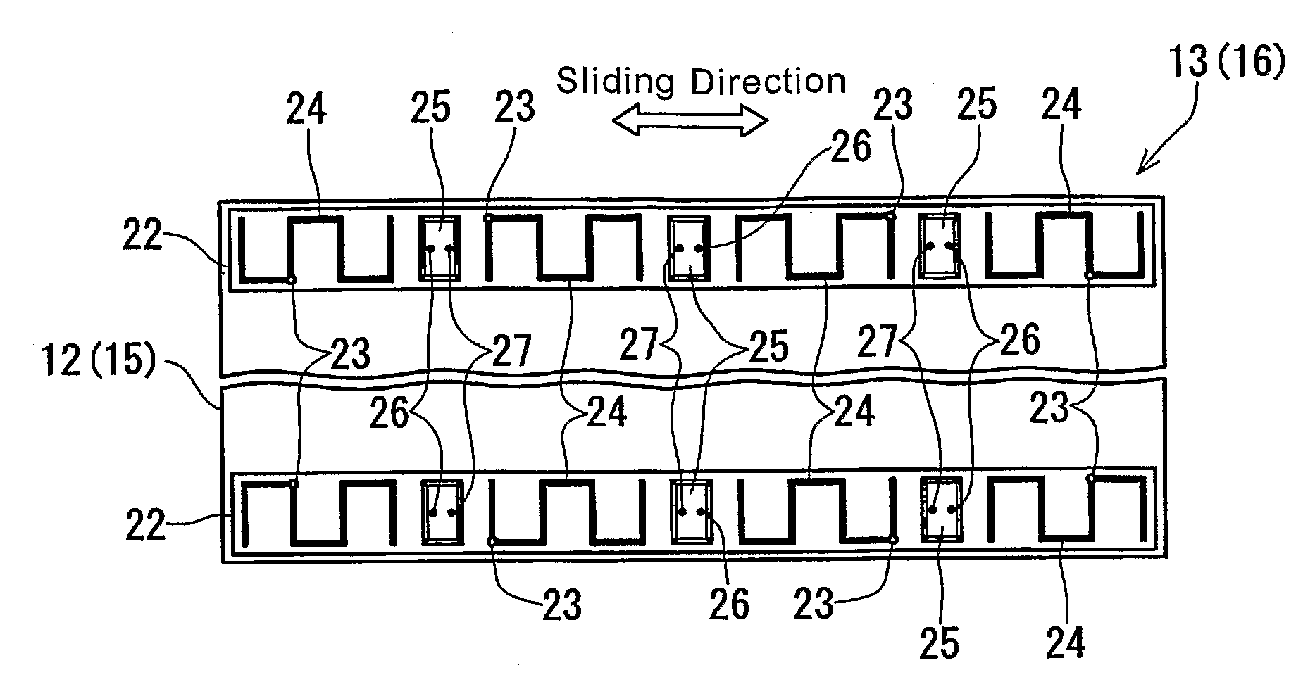
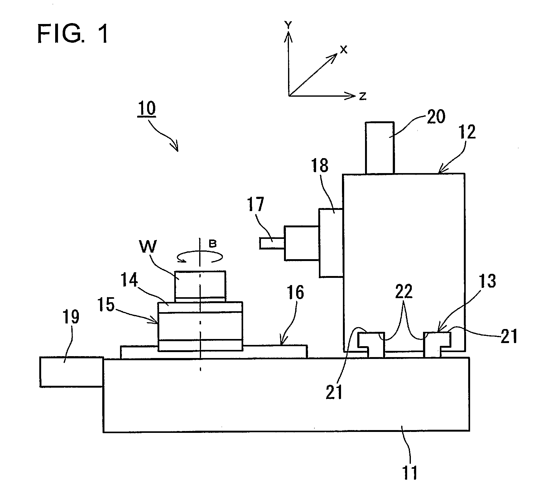
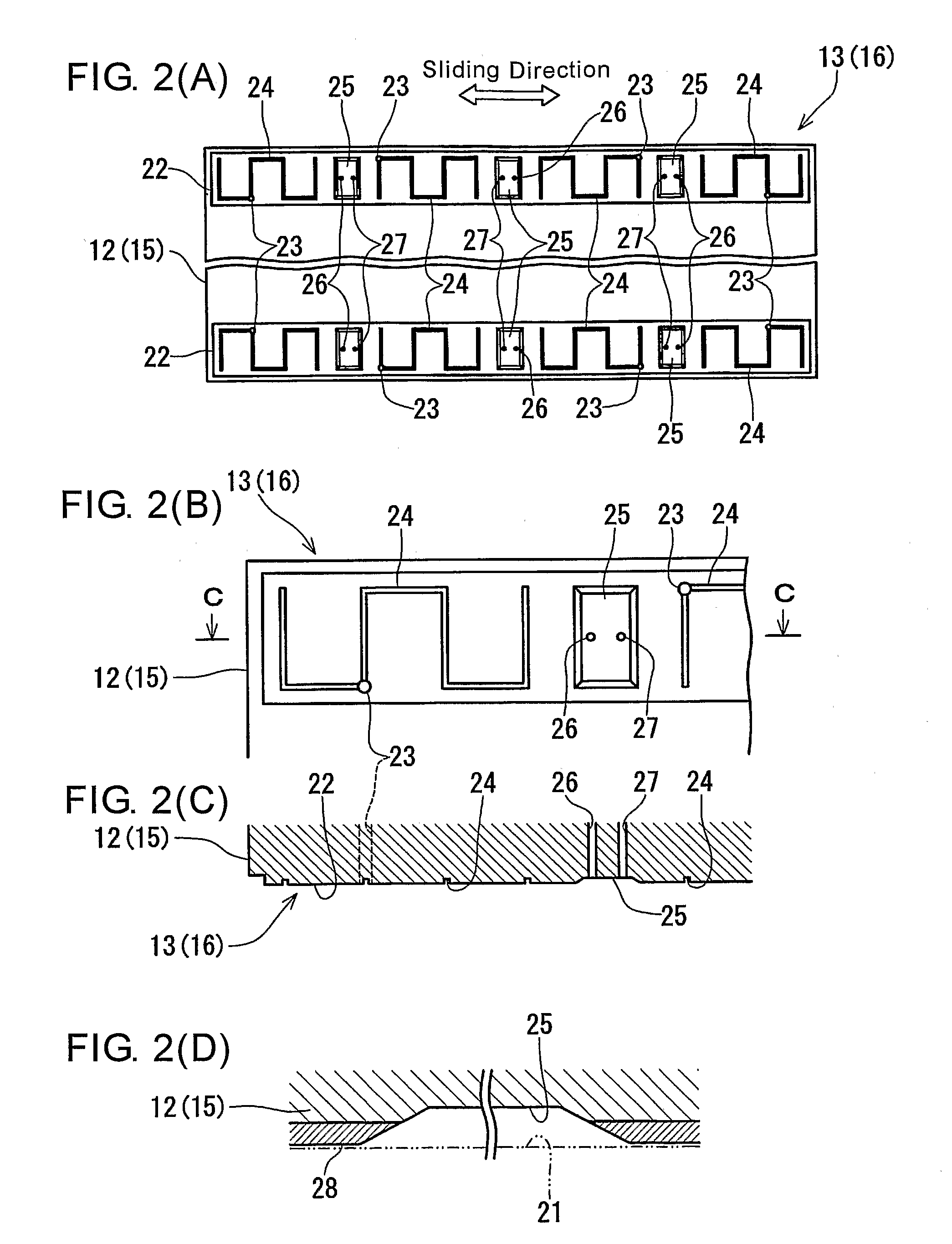
[0038]Hereafter, a slide guiding device in a preferred embodiment according to the present invention will be described with reference to FIG. 1 through FIG. 3. FIG. 1 is a schematic side elevational view of a machine tool to which a slide guiding device according to the present invention is applied, FIG. 2(A) is a schematic bottom surface view of a movable slide having a sliding surface in the slide guiding device according to the present invention, FIG. 2(B) is an enlarged fragmentary view showing a part of the sliding surface in an enlarged scale, FIG. 2(C) is a sectional view taken along the line C-C in FIG. 2(B), and FIG. 2(D) is an enlarge sectional view of an oil pocket. Further, FIG. 3 is an explanatory view showing the feature of a lateral wall shape which is taken by the oil pocket provided in the present invention.

[0039]Referring now to FIG. 1, a machine tool 10 is shown as machining center wherein four axes including a B-axis in addition to an X-axis, a Y-axis and a Z-axi...


PUM


Abstract

A slide guiding device in a machine tool includes slide guiding surfaces provided on a bed, sliding surfaces provided on a column, which is guided on the bed for movement on the same, and movable on the slide guiding surfaces, oil grooves each with a first supply hole for supplying lubrication oil to contact surface areas between the sliding surfaces and the slide guiding surfaces, and oil pockets formed independently of the oil grooves for retaining the lubrication oil supplied to the contact surface areas between the sliding surfaces and the slide guiding surfaces.

Description

TECHNOLOGICAL FIELD[0001]The present invention relates to a slide guiding device for a movable slide as used in machine tools or the like. Particularly, it relates to a slide guiding device which is capable of keeping the lost motion of the movable slide in a proper state by effectively suppressing the occurrence of the lack of lubrication oil even where the time interval for lubrication oil supply is lengthened.BACKGROUND ART[0002]Heretofore, as a slide guiding device for a movable slide as used in machine tools or the like, there has been known one which is provided with a slide guiding surface formed on a support member such as bed or the like and a sliding surface which is formed on a movable slide such as column, saddle, spindle head or the like to be slidable on the slide guiding surface.[0003]In the slide guiding device, the sliding surface has formed thereon oil grooves each with a supply hole for supplying lubrication oil to a contact surface area between the slide guiding ...

Claims


Application Information

Patent Timeline
Patent Type & Authority Patents(United States)
IPC IPC(8): F16C32/06B23Q11/12B23Q1/42F16C29/02F16C33/10
CPCF16C29/025F16C32/0659F16C33/1065F16C33/1075
Inventor SAITO, TOSHIYUKISAKEI, TOSHIKAZUASO, TOMIOHAMAJIMA, YOUJI
Owner JTEKT CORP
Why Eureka
Try Eureka