Ultrasonograph

a technology of ultrasound and ultrasound beam, applied in the field of ultrasound beam, can solve the problems of inability to perform dynamic focusing in reception, new technical problems in transmitting focusing, and inability to change the intensity of ultrasound in the propagation direction, etc., and achieves high lateral resolution, easy control, and uniform width of main beam.

Inactive Publication Date: 2010-08-31
FUJIFILM HEALTHCARE CORP
View PDF28 Cites 40 Cited by
  • Summary
  • Abstract
  • Description
  • Claims
  • Application Information

AI Technical Summary

Benefits of technology

[0014]As described above, in the method of the invention, the amplitude of weighting and the delay time for transmit focusing are changed from element to element, but the waveform itself is not changed. Consequently, a number of transmit focal points can be sufficiently finely set in the ultrasound propagation direction without being influenced by interference between transmit signals corresponding to different transmit focal points. It is therefore expected that a transmit beam having higher uniformity in the width of the main beam can be generated. Since the waveform itself is common to the elements, such a transmit beam can be generated by relatively easy control.

Problems solved by technology

As for transmission, however, the dynamic focusing performed in reception cannot be carried out.
It raises a new technical problem on the transmit focusing.
Specifically, when a single focal length is set and waves are transmitted, changes in the intensity of ultrasound in the propagation direction are not uniform.
In the method, since transmission signals corresponding to different focal points interfere each other, to prevent canceling off, the number of focal points to be set cannot be increased to several points or more.
As a result, the uniformity in the ultrasound propagation direction of the width of the main beam formed is limited, and the control on the transmission waveforms of the elements is also complicated.

Method used


Image

  • Ultrasonograph
  • Ultrasonograph
  • Ultrasonograph

Examples


Embodiment Construction

[0026]An embodiment of the invention will be described hereinbelow with reference to the drawings.

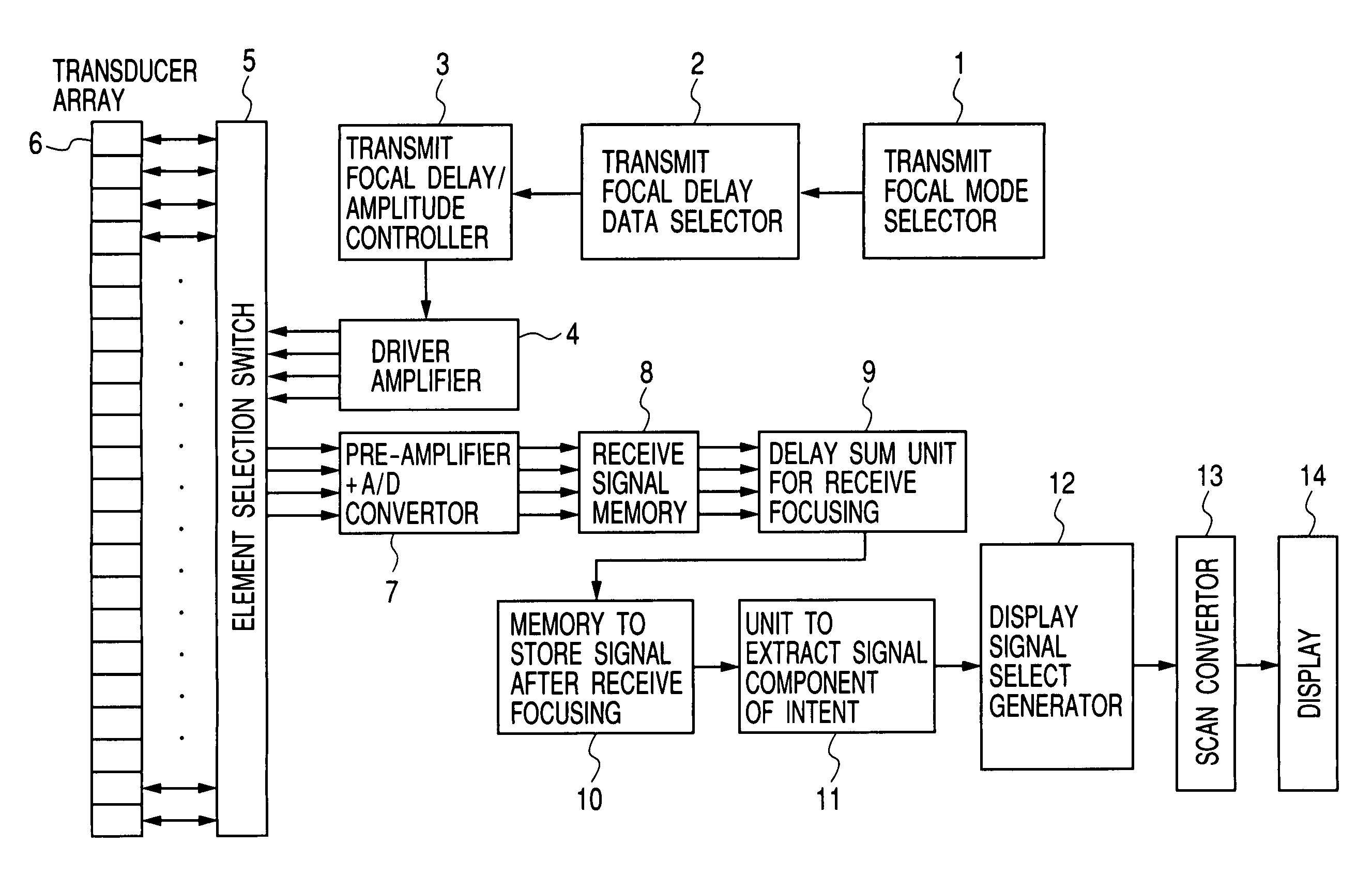
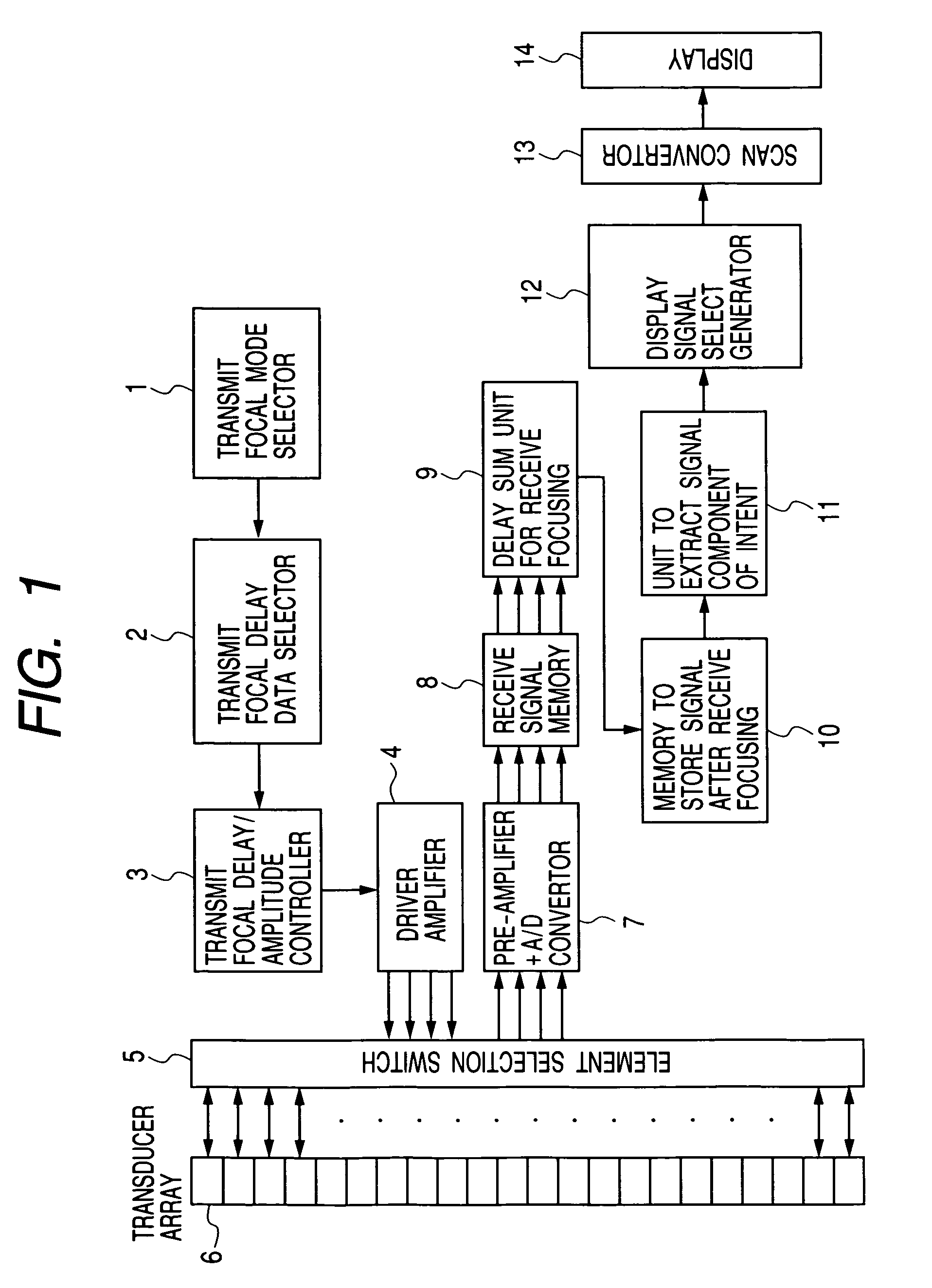
[0027]FIG. 1 is a block diagram showing a typical configuration of an apparatus acquired by applying the invention to an ultrasonic diagnostic system based upon a pulse-echo method.

[0028]A transmit focus mode selector 1 selects transmission of either a transmit beam having a uniform width in an ultrasound propagation direction or a transmission beam having resolution and an S / N ratio which are excellent only around a specific focal length. Based on the selection, a transmit focus delay data selector 2 selects corresponding transmit focus delay data and transmit aperture weight data.

[0029]A transmit focal delay and amplitude controller 3 supplies an input to a drive amplifier 4 at a timing controlled by giving a controlled amplitude to a transmit waveform on the basis of the data. An output of the drive amplifier 4 is transmitted to an element selected by an element selecting switch 5 fr...


PUM

PropertyMeasurementUnit
frequencyaaaaaaaaaa
focal lengthaaaaaaaaaa

Abstract

An ultrasonograph capable of generating a transmission beam comprising a main beam having a uniform width over a wide range in an ultrasonic wave propagation direction by one-time transmission of an ultrasonic pulse. A weighted mean value of a plurality of transmission delay time values corresponding to focal lengths of transmission pulse waves having a plurality of focal points which are set in the ultrasonic wave propagation direction is calculated for each of elements constituting a transmission aperture and used as the delay time. The curvature of a transmitted wave front is close to a short focal length in the center portion of the transmit aperture and is close to a long focal length in the peripheral portion. Thus, a transmission beam including a relatively narrow main beam with a uniform width over a wide range in the ultrasonic wave propagation direction can be generated.

Description

TECHNICAL FIELD[0001]The present invention relates to an ultrasonograph for obtaining an image of the inside of a subject such as a living body by transmitting / receiving an ultrasound to / from the subject.BACKGROUND ART[0002]An ultrasonograph that transmits / receives a pulsed ultrasound to / from a living body and acquires an image of the inside of the living body is widely used in medical diagnosis. It is ideal to set focal points in the transmission / reception of the ultrasound for all of points in a living body in an image acquisition target range, from the viewpoints of both resolution and the S / N ratio of an ultrasound image.[0003]As for reception, with recent advance of the digital circuit technology, in an electronically focused scanner, dynamic focusing of gradually increasing the focal length in accordance with lapse time since transmission of an ultrasound pulse become possible. By the dynamic focusing, images at all of points in a living body in a range of propagation of the u...

Claims


Application Information

Patent Timeline
Patent Type & Authority Patents(United States)
IPC IPC(8): A61B8/00G01S7/52G10K11/34G01N29/26
CPCG01S7/52026G01S7/52038G01S7/52047G01S15/8963G10K11/346A61B8/481G01S7/5202
Inventor UMEMURA, SHIN-ICHIROMIWA, YUICHIAZUMA, TAKASHISUGIYAMA, TAKASHIKURIBARA, HIROSHI
Owner FUJIFILM HEALTHCARE CORP
Why Eureka
Try Eureka