Spherical sand separators

a sand separator and spherical technology, applied in the field of separation, can solve the problems of minimal porousness, inability to readily permit, and rare production from natural gas wells, and achieve the effects of safe operation, excellent results and thin walls

Active Publication Date: 2010-08-31
SAND SEPARATORS
View PDF25 Cites 62 Cited by
  • Summary
  • Abstract
  • Description
  • Claims
  • Application Information

AI Technical Summary

Benefits of technology

[0010]The subject invention provides for an apparatus and methods for separating natural gas from high pressure, high velocity production streams comprising a liquid dispersion of water, sand, and natural gas. The separator comprises a vessel having an interior surface defining a spherical interior space. The interior space allows a production stream introduced therein to experience a velocity drop sufficient to allow separation of the natural gas from the sand and water components. The separator also comprises a stream inlet port in the vessel, a liquid drain in the lower end of the vessel, and a gas outlet port at the upper end of the vessel remote from the stream inlet port. A baffle is mounted in the interior of the vessel in the path of the production stream between the stream inlet port and the gas outlet port. The baffle is effective to spread the flow of and to direct a production stream introduced into the interior space via the stream inlet port downward toward the liquid drain.
[0011]It will be appreciated that such vessels have provided excellent results in separating such high pressure, high velocity production streams. By providing a spherical vessel the novel apparatus may be safely operated at higher pressures relative to comparably fabricated

Problems solved by technology

In practice, however, production from a natural gas well is rarely that simple.
Many formations are minimally porous and do not readily allow gas to flow from the formation to a well bore.
This process tends to “fracture” the formation, i.e., to open up pores and create flow paths from the formation to the production well.
While such techniques are very effective at ultimately increasing the flow of natural gas from a minimally porous formation, they create immediate challenges that must be met.
During the initial phase of production from such wells, however, the stream is typically a liquid dispersion containing not only natural gas, but also large quantities of water, sand, and any other additives that were injected into the well during fracking.
Entrained sand can be very cor

Method used


Image

  • Spherical sand separators
  • Spherical sand separators
  • Spherical sand separators

Examples


Embodiment Construction

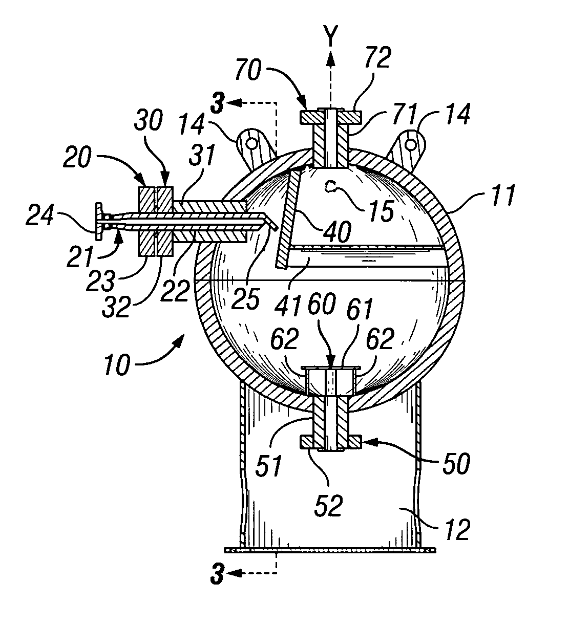
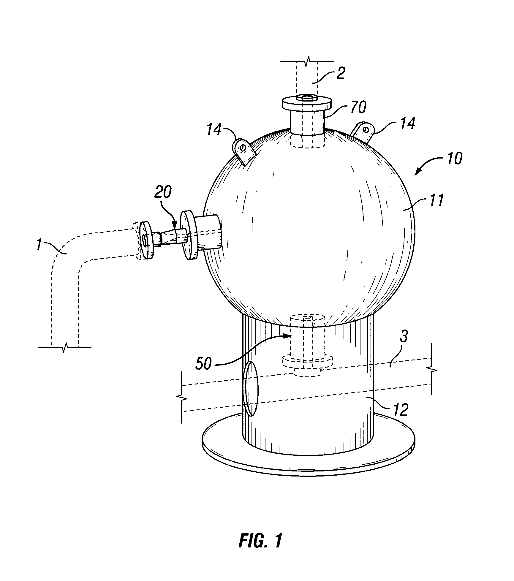
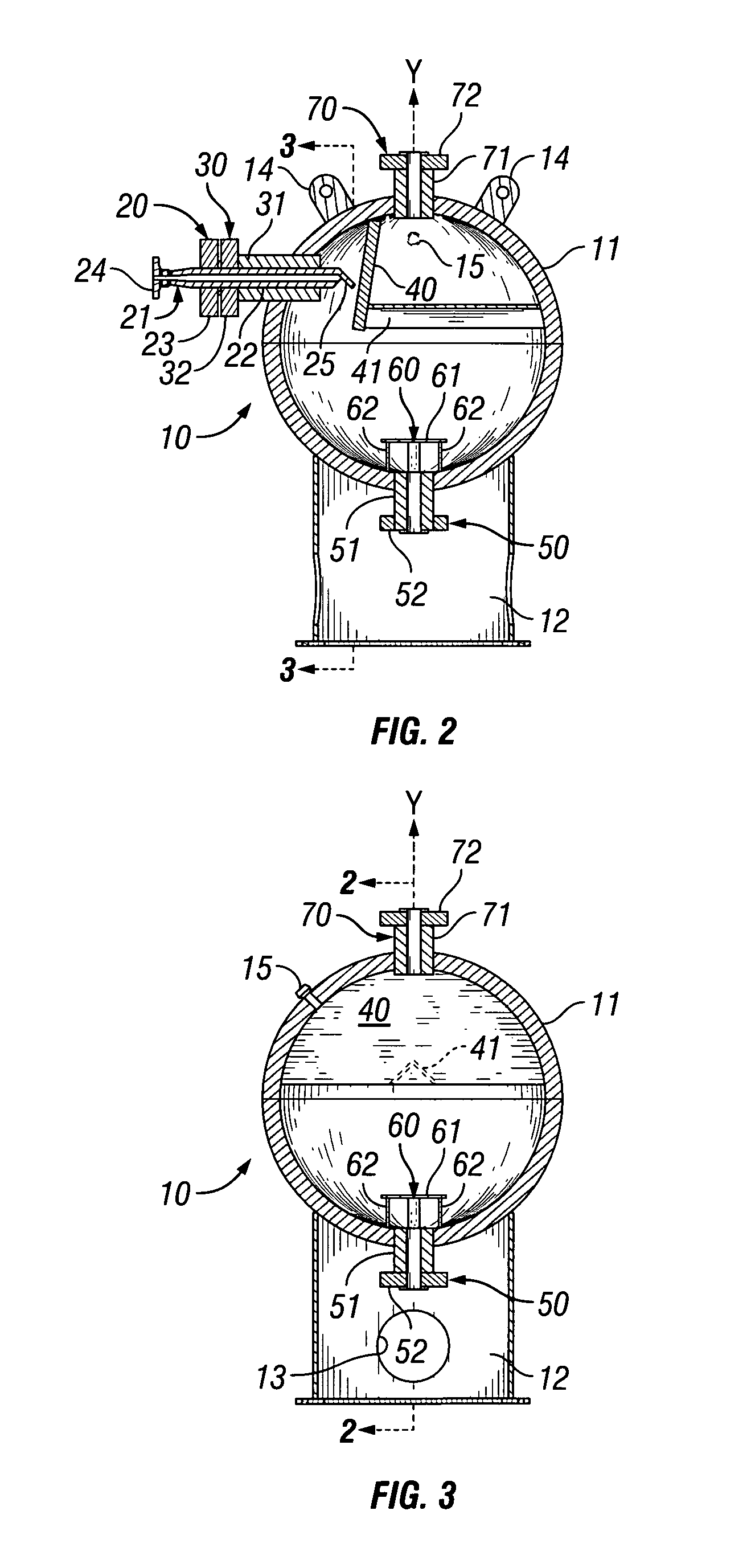
[0020]The apparatus of the subject invention, such as the preferred embodiment 10 illustrated in FIGS. 1-7, are designed to effectively separate natural gas from production streams, especially high pressure, high velocity production streams, comprising water and sand. In particular, they are adapted to handle high pressure, high velocity production streams such as a produced in the early stages of production from a horizontal well that has been fractured. Such streams typically will be produced, at least initially, at pressures in the range of from 3,000 to 5,000 psi, and more and more commonly up to 10,000 psi. The flow rates through a typical 3 or 4 inch production line can approach a million cubic feet per hour or more. It will be readily appreciated that the corresponding velocity of those production streams is extremely high.

[0021]During the initial stages of production the stream from such wells typically is in the form of a liquid dispersion with water being the major phase. ...


PUM

PropertyMeasurementUnit
Angleaaaaaaaaaa
Pressureaaaaaaaaaa
Flow rateaaaaaaaaaa

Abstract

An apparatus for separating natural gas from production streams comprising a liquid dispersion of water, sand, and natural gas is provided for. The separator comprises a vessel having an interior surface defining a spherical interior space. The interior space allows a production stream introduced therein to experience a velocity drop sufficient to allow separation of the natural gas from the sand and water components. The separator also comprises a stream inlet port in the vessel, a liquid drain in the lower end of the vessel, and a gas outlet port at the upper end of the vessel remote from the stream inlet port. A baffle is mounted in the interior of the vessel in the path of the production stream between the stream inlet port and the gas outlet port. The baffle is effective to spread and direct a high pressure production stream introduced into the interior space via the stream inlet port downward toward the liquid drain.

Description

FIELD OF THE INVENTION[0001]The present invention relates to separators used in natural gas well completion and production operations and, and more particularly, to spherical sand separators particularly suited for use in separating natural gas from high pressure, high velocity production streams containing relatively large quantities of water and sand.BACKGROUND OF THE INVENTION[0002]Hydrocarbons, such as oil and gas, may be recovered from various types of subsurface geological formations. Such formations typically consist of a porous layer, such as limestone and sands, overlaid by a nonporous layer. Hydrocarbons cannot rise through the nonporous layer, and thus, the porous layer forms a reservoir in which hydrocarbons are able to collect. A well is drilled through the earth until the hydrocarbon bearing formation is reached. Hydrocarbons then are able to flow from the porous formation into the well.[0003]In practice, however, production from a natural gas well is rarely that simpl...

Claims


Application Information

Patent Timeline
IPC IPC(8): B01D19/00
CPCB01D19/0042B01D45/08B01D45/12
Inventor WORLEY, EMMETT RONALDGREEN, SHIRLEY ROYCE
Owner SAND SEPARATORS
Why Eureka
Try Eureka