Determination of the outline of an elevated object

Inactive Publication Date: 2010-08-31
LOCKHEED MARTIN CORP
View PDF12 Cites 37 Cited by
  • Summary
  • Abstract
  • Description
  • Claims
  • Application Information

AI Technical Summary

Problems solved by technology

Objects in near-Earth space may lie in the earth's umbra or shadow, and thus may not be observable directly or by means of a telescope.
Even when illuminated, details of an object in near Earth

Method used


Image

  • Determination of the outline of an elevated object
  • Determination of the outline of an elevated object
  • Determination of the outline of an elevated object

Examples


Embodiment Construction

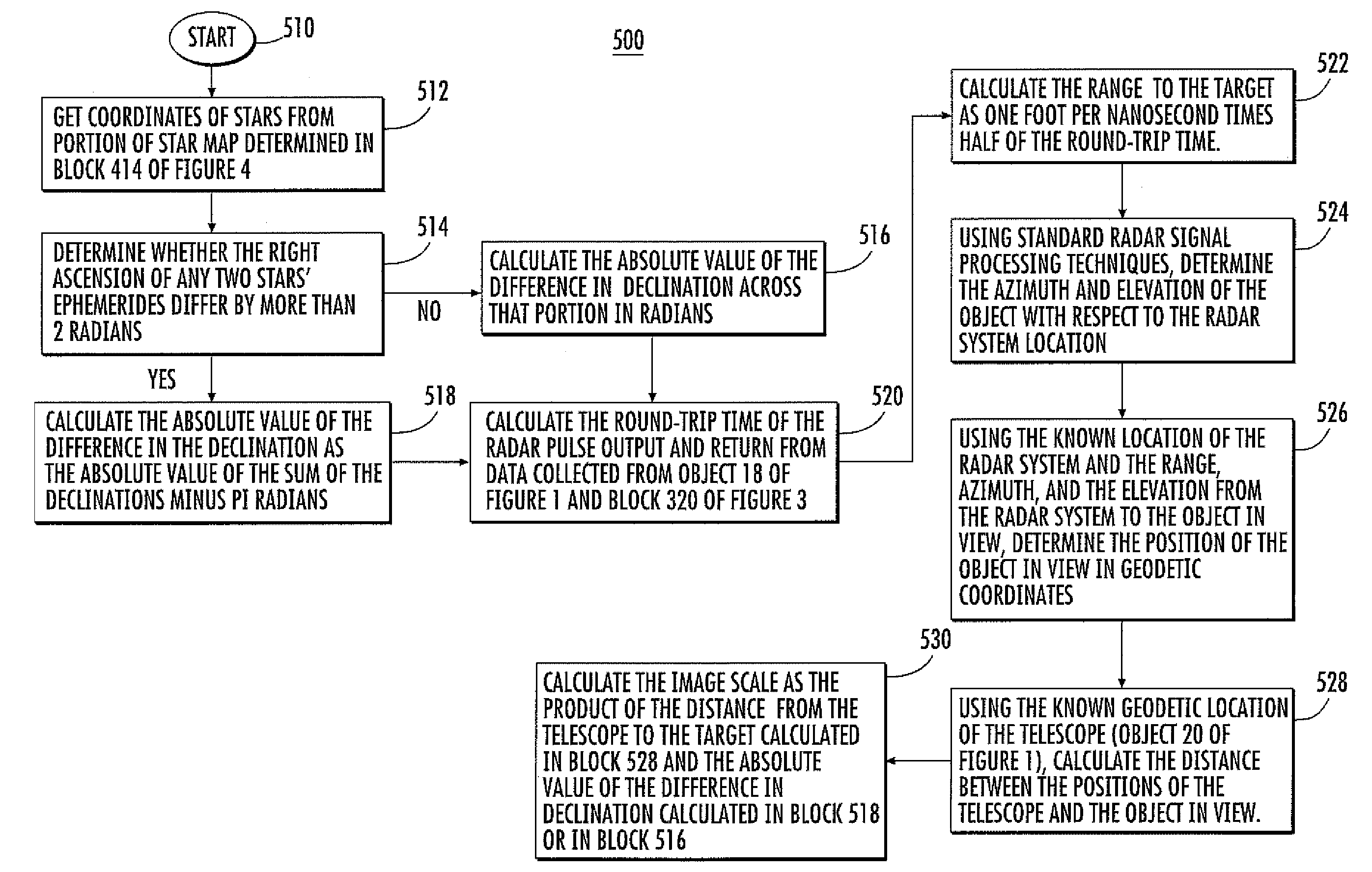
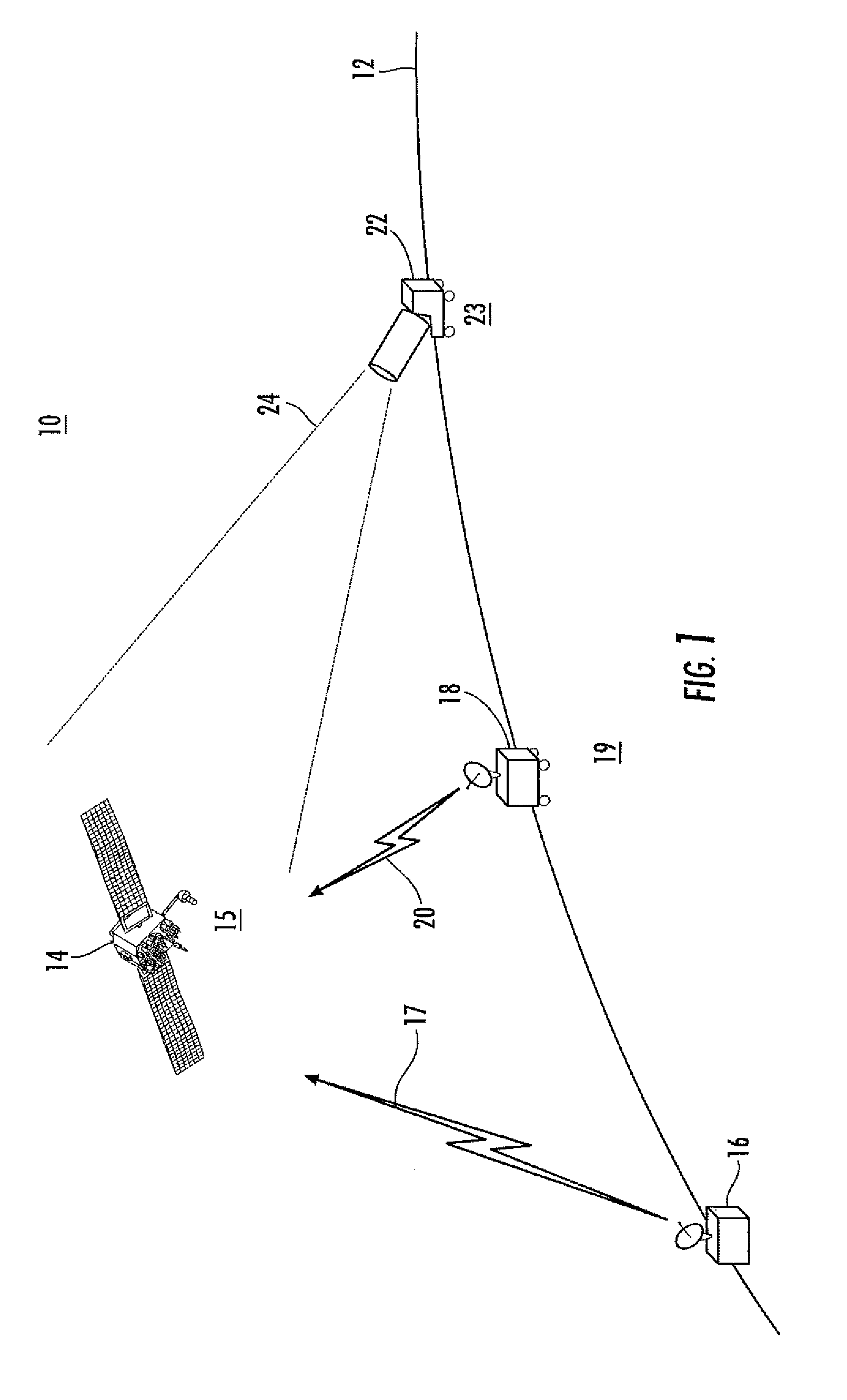
[0012]In scenario 100 of FIG. 1, the Earth's horizon is designated as 12, and a near-Earth-orbit object illustrated as 14 lies in a region 15 of Earth's shadow or umbra. That is, the sun is on the other side of the Earth from that illustrated, so object 14 is in eclipse. A volume scanning radar illustrated as 16 uses radar signals illustrated by a lightning bolt symbol 17 to determine the ephemeris of the object 14. Ephemeris means a table of values which gives the position of astronomical objects in the sky at a given time or times. Thus, operation of the radar system 16 establishes the general orbital location of object 14.

[0013]Also in FIG. 1, another radar system (or possibly the same as radar system 16) illustrated as 18 is placed at a location 19, at which location it is capable of viewing the region occupied by object 14. The coordinates of location 19 must be known, as for example by use of a global positioning system (GPS), and the orientation of the radar 18 must also be k...


PUM


Abstract

A method and apparatus determines the shape of an orbiting or airborne object. A radar determines the general location and a telescope is directed toward the object to form an image of background stars, which will be occluded by the object. The image is compared with a memorized star map, to identify the region of the image in the map. Stars visible in the map which are not visible in the image are listed. The invisible stars are paired with next adjacent visible stars to form star pairs. The midpoints are identified of lines extending between star pairs. Segment lines are drawn between a midpoint and the next closest midpoint. The segment lines define an outline of the object.

Description

BACKGROUND OF THE INVENTION[0001]Determination of the status of spacecraft has been determined in the past by reporting by telemetry on measurements performed on the spacecraft, by direct observation, and by radar and telescopic viewing. Objects in near-Earth space may lie in the earth's umbra or shadow, and thus may not be observable directly or by means of a telescope. Even when illuminated, details of an object in near Earth space may be difficult or impossible to view, as light from the illuminating source may impinge on the side facing away from the viewer, so that the observable side of the object is in shadow.[0002]Improved or alternative methods for viewing near-Earth-space objects is desired.SUMMARY OF THE INVENTION[0003]A method according to an aspect of the invention is for determining the projected shape of an object in an Earth orbit, where the orbit includes periods of time in which the object is in Earth's umbra or shadow. The method comprises the steps of radar track...

Claims


Application Information

Patent Timeline
IPC IPC(8): G01S13/89G01S13/86
CPCB64G3/00G01S13/86G06T7/0042G06T7/0081G01S2013/029G06T2207/10004G06T2207/20144G06T7/11G06T7/194G06T7/73
Inventor KNIBBE, PETER W.STETSON, JOHN B.
Owner LOCKHEED MARTIN CORP
Why Eureka
Try Eureka