Polar loop radio frequency (RF) transmitter having increased dynamic range amplitude control

a radio frequency (rf) transmitter and dynamic range technology, applied in power management, amplitude demodulation, baseband system details, etc., can solve the problems of high linear power amplifiers, inefficient highly linear power amplifiers, and inability to adapt existing gsm transmitter hardware to transmit signals, etc., to achieve the effect of reducing gain

Active Publication Date: 2010-08-31
SKYWORKS SOLUTIONS INC
View PDF28 Cites 45 Cited by
  • Summary
  • Abstract
  • Description
  • Claims
  • Application Information

AI Technical Summary

Problems solved by technology

Unfortunately, existing GSM transmitter hardware is not easily adapted to transmit a signal that includes both a PM component and an AM component.
Unfortunately, highly linear power amplifiers are very inefficient, thus consuming significantly more power than a non-linear power amplifier and drastically reducing the talk-time and standby time of the portable communication device on a battery charge.
This condition is further complicated because GSM transmitters transmit in bursts and must be able to control the ramp-up of the transmit power as well as have a high degree of control over the output power level over a wide power range.
Unfortunately, this requires the use of a power amplifier with a highly linear control characteristic and wide dynamic control range.
In general the highly efficient power amplifiers used in GSM transmitters do not normally exhibit these properties to a sufficient degree.
Unfortunately, these methods are costly and inefficient.
Further, in those transmission standards in which the signal sent to a power amplifier contains both a PM and an AM component, unless the power amplifier is very linear, it may distort the combined transmission signal by causing undesirable AM to PM conversion.
This conversion is detrimental to the transmit signal and can require the use of a costly and inefficient linear power amplifier.
Further still, in transmission systems in which a combined AM and PM signal is used in a closed power control loop, it is difficult to obtain the full dynamic range in the AM signal to encompass all output power levels and to obtain sufficient dynamic range to smoothly control the ramp-up and ramp-down of the output power.

Method used


Image

  • Polar loop radio frequency (RF) transmitter having increased dynamic range amplitude control
  • Polar loop radio frequency (RF) transmitter having increased dynamic range amplitude control
  • Polar loop radio frequency (RF) transmitter having increased dynamic range amplitude control

Examples


Embodiment Construction

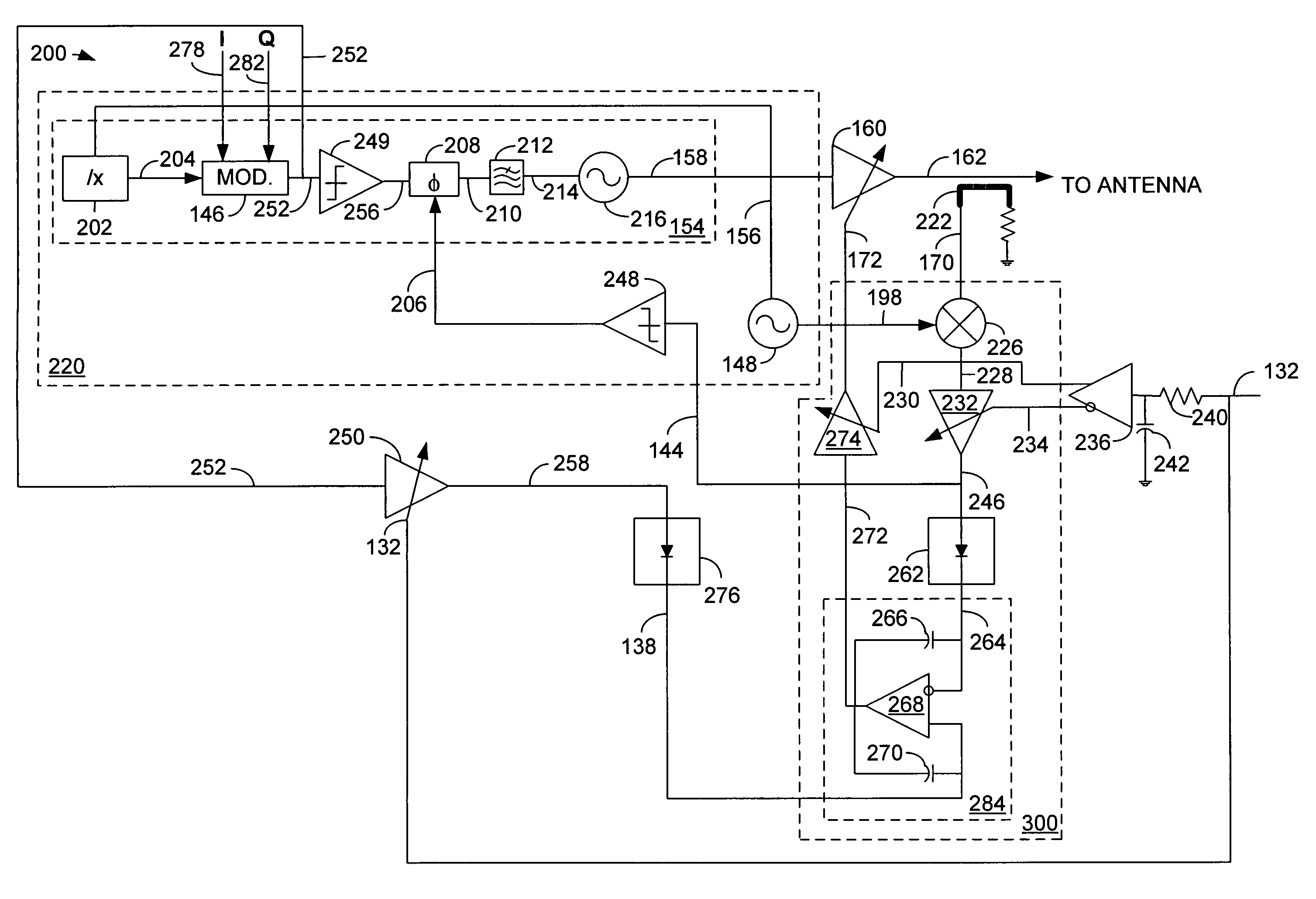
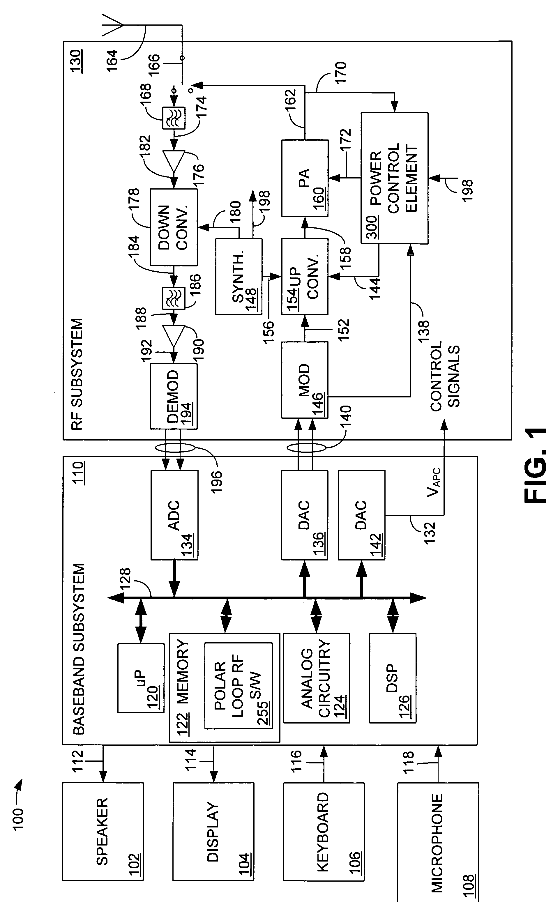
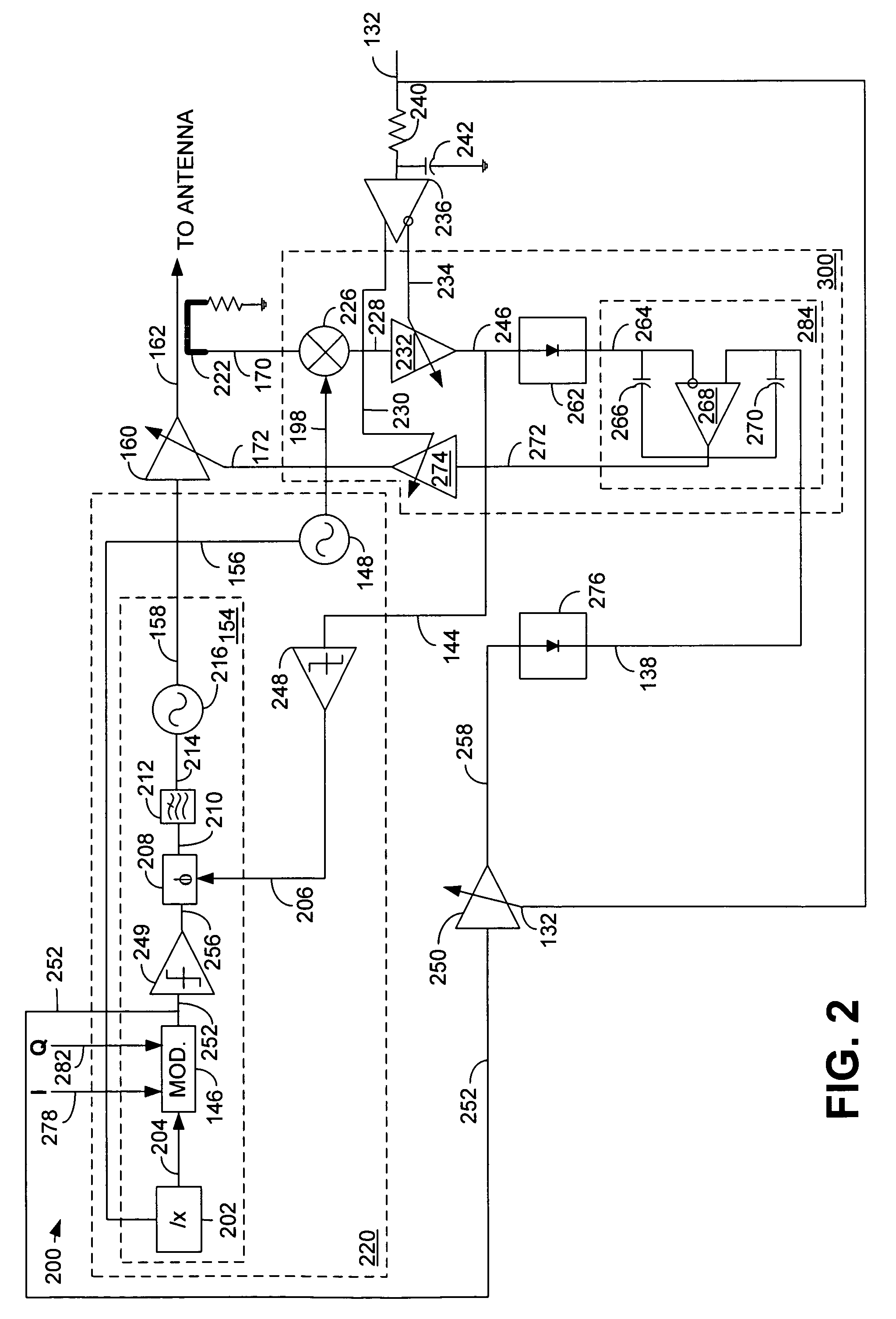
[0019]Although described with particular reference to a portable transceiver, the polar loop RF transmitter having increased dynamic range amplitude control can be implemented in any system where it is desirable to transmit a combined signal including a PM component and an AM component and maintain high dynamic range control over the AM signal.

[0020]The polar loop RF transmitter having increased dynamic range amplitude control can be implemented in hardware, software, or a combination of hardware and software. When implemented in hardware, the polar loop RF transmitter having increased dynamic range amplitude control can be implemented using specialized hardware elements and logic. When the polar loop RF transmitter having increased dynamic range amplitude control is implemented partially in software, the software portion can be used to precisely control the AM signal in the power control loop. The software can be stored in a memory and executed by a suitable instruction execution s...


PUM


Abstract

A closed loop power control system for a radio frequency (RF) transmitter comprises a first variable gain element located in a power control loop and configured to receive a power level signal and an inverse representation of a power control signal, a second variable gain element located in the power control loop and configured to receive an error signal and the power control signal, and a third variable gain element configured to receive an amplitude modulated (AM) signal and the power control signal, the third variable gain element having a gain characteristic configured to operate to reduce the gain applied to the AM signal when the power control signal falls below a minimum predetermined value, and to provide the AM signal as a reference signal.

Description

BACKGROUND OF THE INVENTION[0001]1. Field of the Invention[0002]This invention relates generally to transceiver architecture in a wireless portable communication device. More particularly, the invention relates to a polar loop transmitter having increased dynamic range amplitude control.[0003]2. Related Art[0004]Radio frequency (RF) transmitters are found in many one-way and two-way communication devices, such as portable communication devices (cellular telephones), personal digital assistants (PDAs) and other communication devices. An RF transmitter must transmit using whatever communication methodology is dictated by the particular communication system within which it is operating. For example, communication methodologies typically include amplitude modulation, frequency modulation, phase modulation, or a combination of these. In a typical global system for mobile communications (GSM) communication system using narrowband TDMA technology, a GMSK modulation scheme supplies a low no...

Claims


Application Information

Patent Timeline
Patent Type & Authority Patents(United States)
IPC IPC(8): H03D1/24
CPCH03C1/00H03G3/3047H04L27/08H04L27/3809H04W52/06H04L27/361H04W52/36H04L25/49H04L27/04H04B1/04
Inventor ROZENBLIT, DMITRIYSOWLATI, TIRDADDAMGAARD, MORTEN
Owner SKYWORKS SOLUTIONS INC
Why Eureka
Try Eureka