
RF connector assembly

a technology of rf connectors and connector assemblies, which is applied in the direction of coupling device details, coupling device connections, two-pole connections, etc., can solve the problems of unreliable engagement between electrical connectors and complementary connectors, difficult to provide a controllable twisting force for complementary connectors, etc., and achieves reliable engagement

Inactive Publication Date: 2010-09-07
HON HAI PRECISION IND CO LTD
View PDF8 Cites 17 Cited by
  • Summary
  • Abstract
  • Description
  • Claims
  • Application Information

AI Technical Summary

Benefits of technology

The present invention provides an RF connector assembly that ensures reliable connection between two connectors. The assembly includes a first connector with an insulative member, center conductor, flexible bushing, and magnetic member, and a second connector with a mating member that is firmly resisted by the flexible bushing. When the second connector is screwed into the first connector, the mating member is sucked by the magnetic member, strengthening the connection. The flexible bushing effectively controls the twisting movement of the mating member during backward and forward movement of the second connector.

Problems solved by technology

It is difficult to provide a controllable twisting force for the complementary connector due to a tolerance of the flexible tubular.
Thus, the engagement between the electrical connector and the complementary connector is unreliable.

Method used


Image

  • RF connector assembly
  • RF connector assembly
  • RF connector assembly

Examples


Embodiment Construction

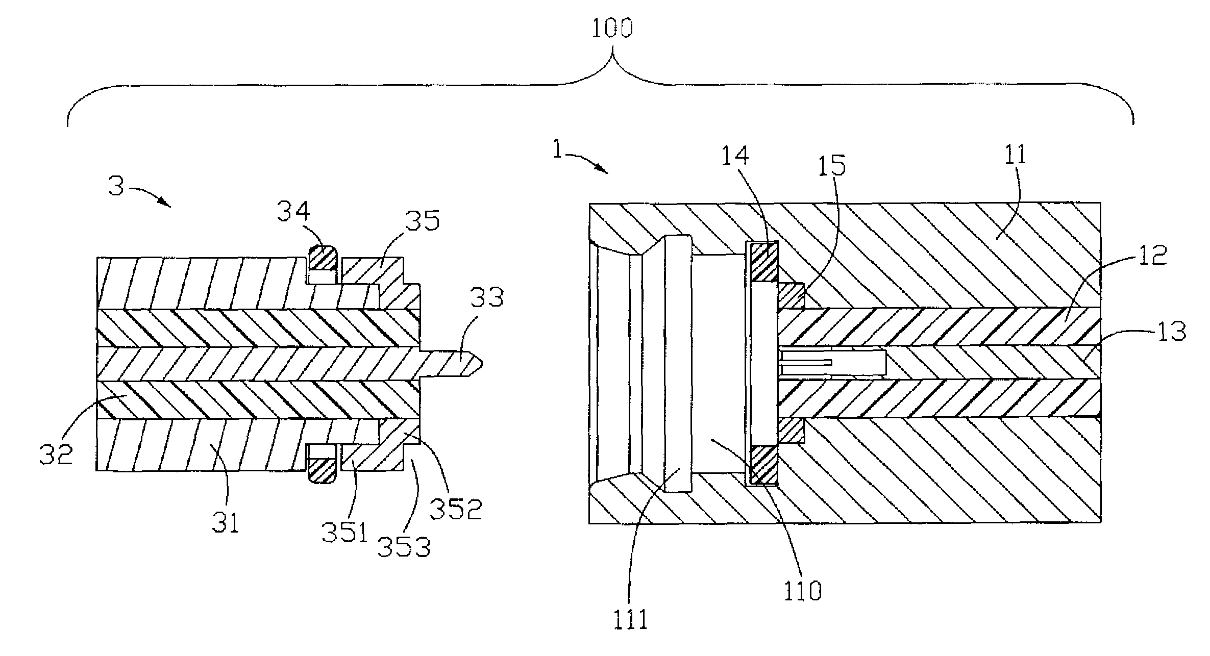
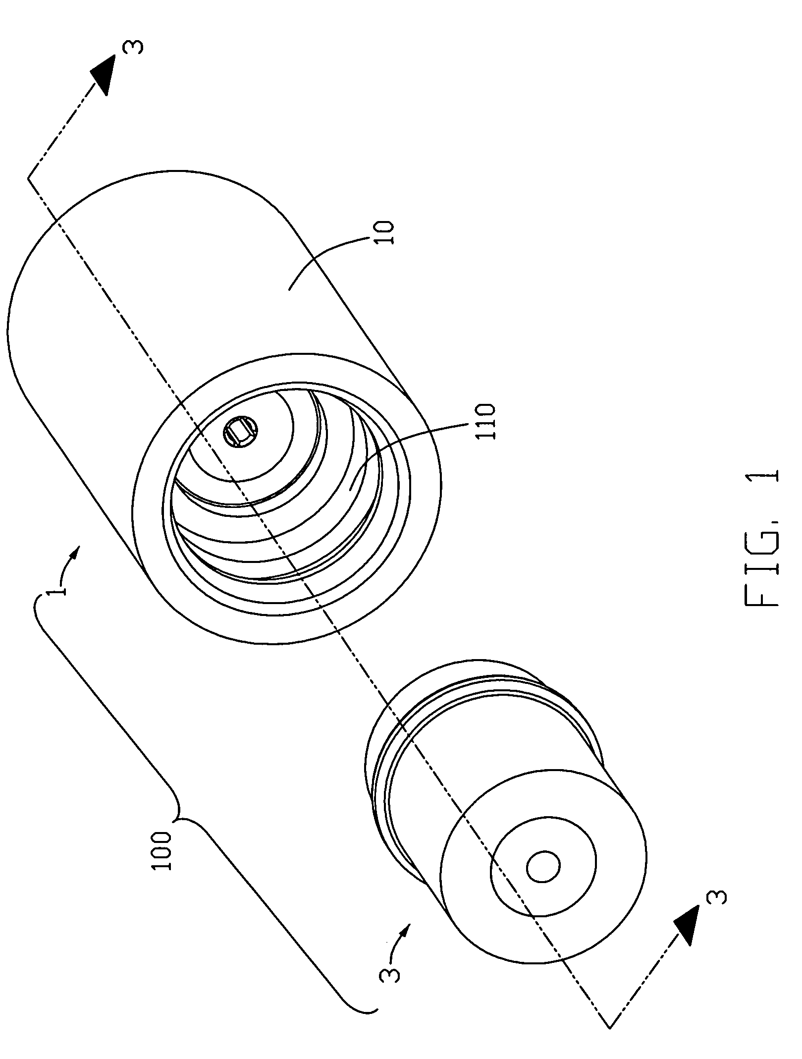
[0014]Reference will now be made to the drawing figures to describe the present invention in detail. Referring to FIGS. 1-3, an RF connector assembly 100 comprises a first connector 1 and a second connector 3 for mating with the first connector 1.

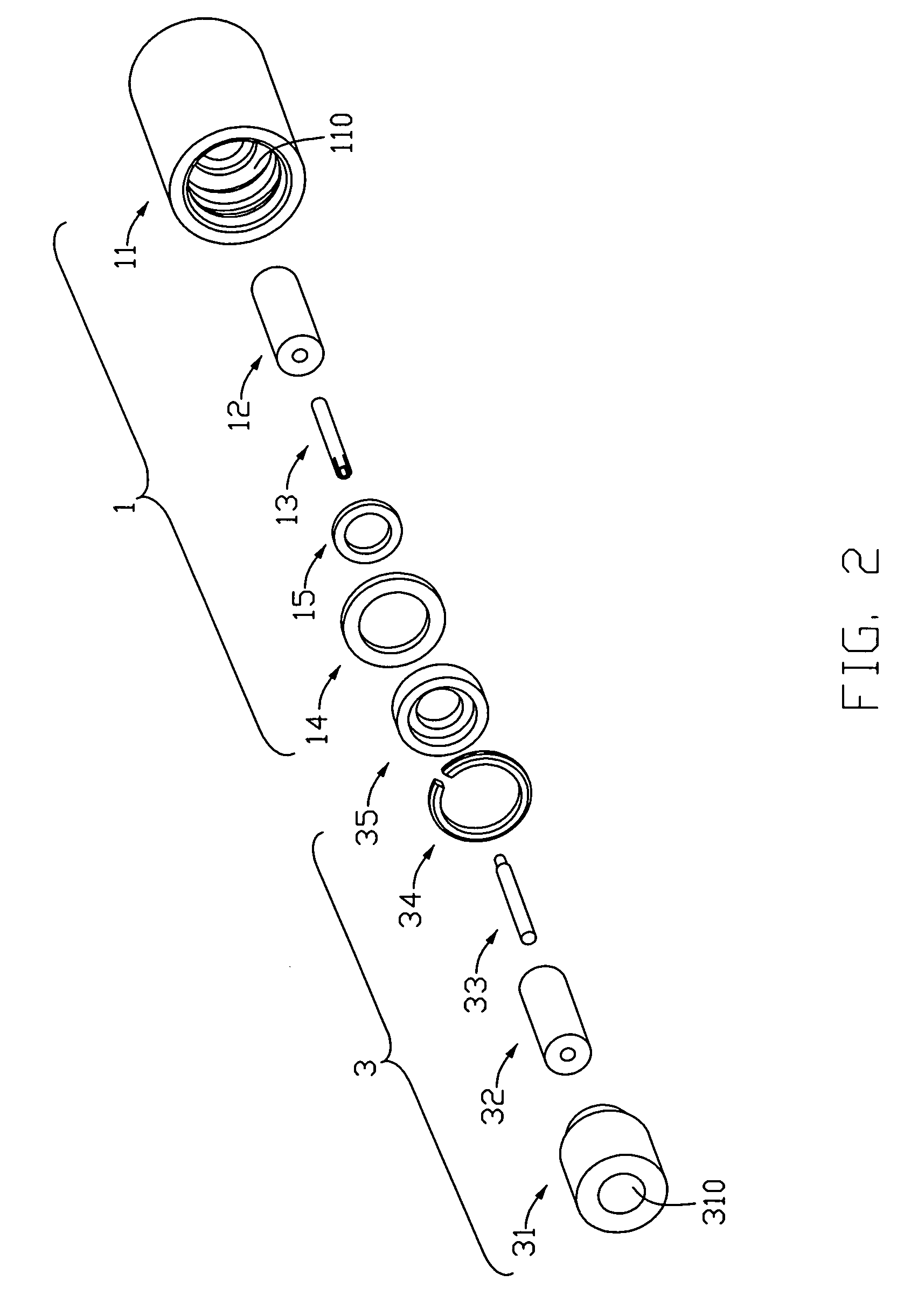
[0015]Referring to FIGS. 2-3, a first connector 1 has a first main body 11 defining an interior space 110, an insulative member 12 received in the interior space 110, a center conductor 13 retained within the insulative member 12, a flexible bushing 14 and a magnetic member 15 retained in the interior space 110. The first main body 11 comprises an annular recess (not labeled) defined in the inner surface thereof and in communication with the interior space 110, and a receiving room 111 defined therein. The flexible bushing 14 is retained in the annular recess.

[0016]The second connector 3 comprises a second main body 31 defining an axial bore 310, an insulator 32 received in the axial bore 310, a central terminal 33 extending through the ins...


PUM


Abstract

An RF connector assembly (100) assembly has a first connector and a second connector (3) electrically connecting with the first connector. The first connector includes a first main body (11) defining an interior space (110), an insulative member (12) received in the interior space, a center conductor (13) retained within the insulative member, a flexible bushing (14) and a magnetic member (15) retained in the interior space. The second connector includes a mating member (35) firmly resisting against the flexible bushing under an attractive force exerted by the magnetic member.

Description

BACKGROUND OF THE INVENTION[0001]1. Field of the Invention[0002]The present invention relates to an RF (Radio Frequency) connector assembly, and more particularly to an RF connector assembly having a magnetic member.[0003]2. Description of the Prior Art[0004]Taiwan Patent No. M257018 issued on Feb. 11, 2005 discloses an RF cable connector assembly for transmitting RF signal and comprising an electrical connector and a mating connector. The electrical connector has a first main body defining a hollow, an insulative member received in the hollow, a center conductor retained within the insulative member, and a flexible tubular received in the hollow. The complementary connector screws into the hollow of the first mating member and provides a front mating shoulder for resisting against the flexible tubular. The flexible tubular provides a twisting force for the complementary connector during a backward and forward twisting movement of the complementary connector. It is difficult to prov...

Claims


Application Information

Patent Timeline
Patent Type & Authority Patents(United States)
IPC IPC(8): H01R11/30
CPCH01R13/6205H01R24/40H01R13/6277H01R2103/00
Inventor ZHU, QING-MANZHANG, XUE-LIANGWANG, CHIEN-CHIUNG
Owner HON HAI PRECISION IND CO LTD
Learn More