Apparatuses and methods for detecting an analyte

Active Publication Date: 2010-09-07
TRACE ANALYTICS
View PDF13 Cites 0 Cited by
  • Summary
  • Abstract
  • Description
  • Claims
  • Application Information

AI Technical Summary

Benefits of technology

[0009]An object of the present invention was accordingly to provide an apparatus and a method for detecting an analyte. The apparatus should be of as simple a design as possible, should be easy to maintain, should permit a rapid measurement of an analyte concentration, and should as far as possible be suitable for use in treating a human or animal and / or should have an adjustable sensitivity.

Problems solved by technology

It has however been found disadvantageous, in particular when monitoring a bioreactor, that with this design of analysis apparatus it is no longer possible to dilute the analyte to be analysed.
This is particularly disadvantageous when monitoring biotechnological and medical processes, for example in a continuous monitoring of the blood sugar level of a diabetic patient.
A disadvantage of this apparatus however is that the very thin flexible tube generates a very high transport resistance and therefore pressure, which means that there is a danger that the dialysis membrane or the flexible tube will rupture.
A further disadvantage is the fact that there is no possibility of carrying out a null line (base line) adjustment of the sensor during the operation of the analysis apparatus.
There is therefore the danger that the measurement accuracy of the sensor will be impaired over long periods of use.
A disadvantage of this method is on the one hand the relatively slow cycle time of 9 minutes, and on the other hand also the complicated control of the method and the high consumption of dialysis fluid due to repeated administration of a dialysis solution of known glucose concentration.
The disadvantage however is that due to the closed cycle of the dialysis fluid during the conventional operation of such an apparatus.
Due to the high operation stress on the sensor there is also the danger that the latter will quickly become inactivated.
The disadvantage in this case is that the measurement accuracy depends on the pumping rate of the infused heparin solution.
In addition there are no possibilities of performing calibrations.
The disadvantage of this arrangement is the complicated construction of the apparatus and the need to force the ultrafiltrate back into the ultrafiltration unit for purposes of calibration.

Method used


Image

  • Apparatuses and methods for detecting an analyte
  • Apparatuses and methods for detecting an analyte
  • Apparatuses and methods for detecting an analyte

Examples


Embodiment Construction

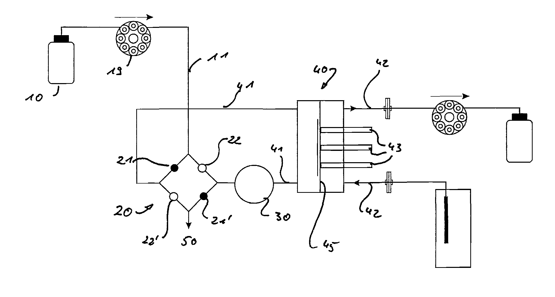
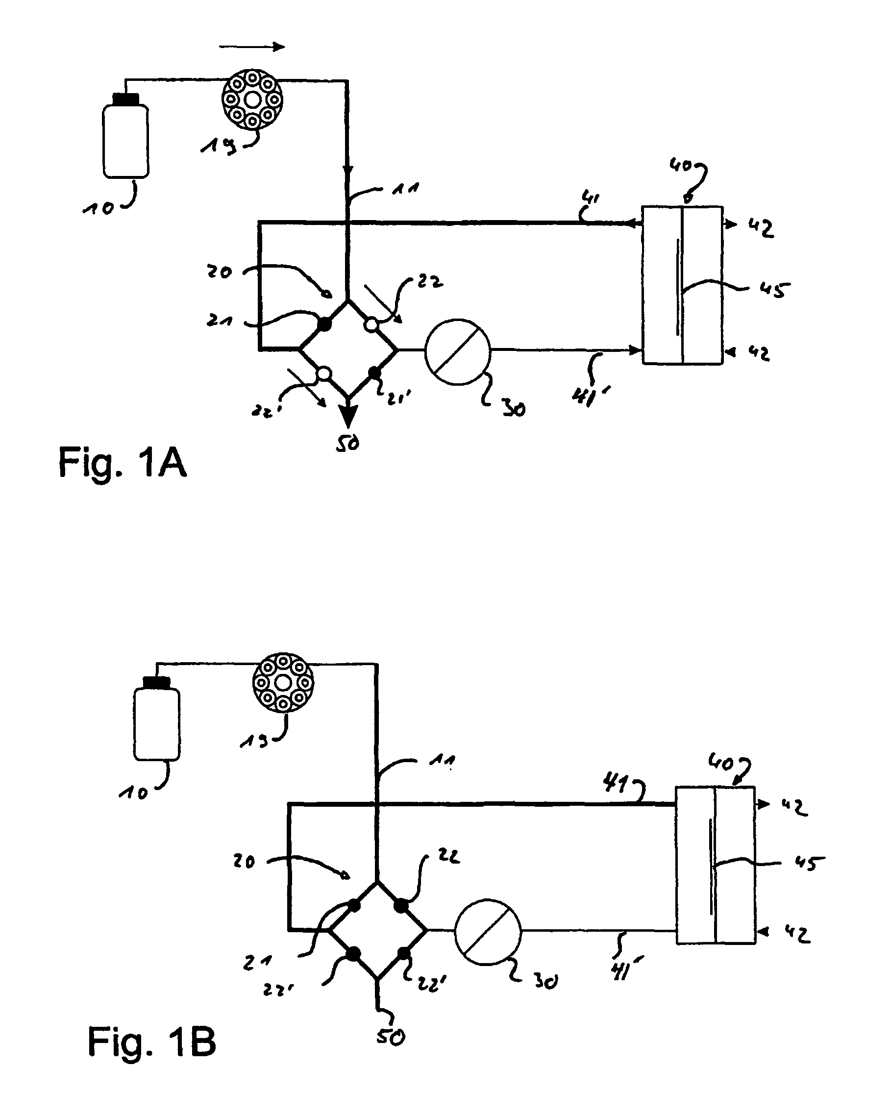
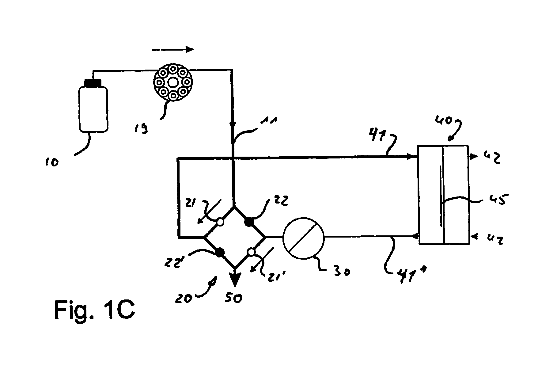
[0017]The apparatus according to the invention enables in a simple way the fluid volume between the analyte feed chamber and sensor chamber to be kept low and accordingly enables a rapid determination of the analyte concentration to be carried out. In addition the sensor chamber and the analyte feed chamber can be completely rinsed out with a very small volume of a rinse liquid, which also contributes to a rapid measurement of an analyte concentration. In addition the apparatus also enables the sensor to be re-calibrated by using a suitably calibrated solution when rinsing the sensor chamber, and thereby enables the measurement accuracy of the apparatus according to the invention to be maintained at a permanently high level. The apparatus according to the invention is in addition of very simple design and construction and is accordingly easy to operate and maintain.

[0018]By using switchable isolating means it is possible to reverse the flow direction of the transport medium in the s...


PUM


Abstract

A method and apparatus for detecting an analyte includes a sensor chamber for detecting an analyte, an analyte feed chamber, a distributor, and a controller for controlling the transport medium flow. The distributor includes an annular channel with four connections with a switchable isolating device between two connections. The controller controls the distributor for flushing the transport medium fed from the distributor to the sensor chamber without passing through the analyte feed chamber and for measuring the transport medium fed from the distributor to the sensor chamber while passing through the analyte feed chamber.

Description

FIELD OF THE INVENTION[0001]The present invention relates to apparatuses and methods for detecting an analyte.BACKGROUND OF THE INVENTION[0002]In process technology and medicine it is often necessary to determine the presence and possibly also the concentration of a preselected analyte rapidly and as continuously as possible. A number of probes and sensors are used for this purpose. For example, an immersion probe is known from WO 00 / 25107, which is immersed in an analyte containing medium—for example the interior of a bioreactor—and an analyte is detected therein. The immersion probe is separated from the medium to be analysed by a membrane that is permeable to the analyte. It has however been found disadvantageous, in particular when monitoring a bioreactor, that with this design of analysis apparatus it is no longer possible to dilute the analyte to be analysed. Accordingly, only those sensors whose maximum measurement range is greater than the highest analyte concentration to be...

Claims


Application Information

Patent Timeline
IPC IPC(8): C12M3/00
CPCA61B5/1486A61B5/415A61B5/1427Y10T436/143333Y10T436/117497Y10T436/17Y10T436/16Y10T436/144444Y10T436/204165A61B5/15003A61B5/150221A61B5/150229A61B5/153A61B5/155A61B5/14528A61B5/14532A61B5/14865A61B5/686
Inventor KUNNECKE, WOLFGANGHARTLEP, MICHAELGIESENBERG, JENS
Owner TRACE ANALYTICS
Why Eureka
Try Eureka