Partial coherence interferometer with measurement ambiguity resolution

a coherence interferometer and resolution technology, applied in the field of partial coherence interferometry and the resolution of ambiguities, can solve the problem that the range sensor is generally inadequate for covering the larger range of measurement with high resolution

Active Publication Date: 2010-09-07
QUALITY VISION INT
View PDF21 Cites 9 Cited by
  • Summary
  • Abstract
  • Description
  • Claims
  • Application Information

AI Technical Summary

Problems solved by technology

However, these range sensors are generally inadequate for covering larger ranges of measurement with high resolution and are more disturbed by irregular surfaces including surfaces with tool marks or other artifacts of roughness, i.e., surfaces having peak to valley roughness of at least ⅛ wavelength of the measuring beam.

Method used


Image

  • Partial coherence interferometer with measurement ambiguity resolution
  • Partial coherence interferometer with measurement ambiguity resolution
  • Partial coherence interferometer with measurement ambiguity resolution

Examples


Embodiment Construction

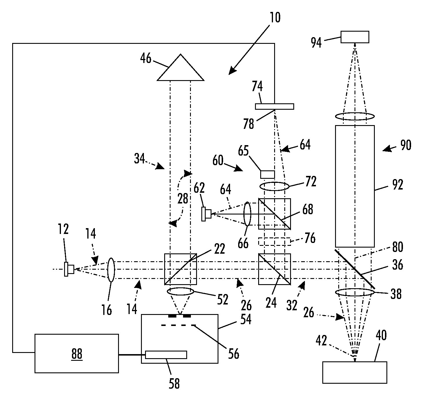
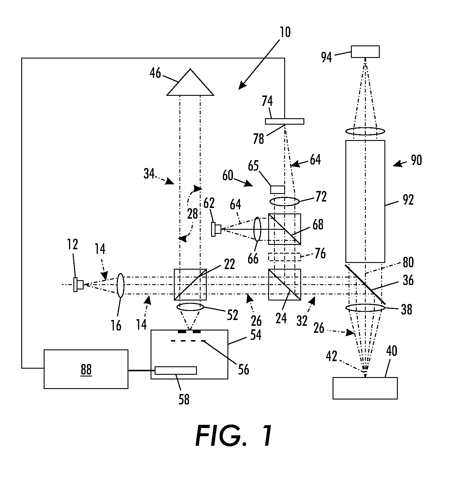
[0019]A partial coherence interferometer 10, as shown in FIG. 1, includes a light source 12 for generating a measuring beam 14 having given spectral bandwidth, preferably within the visible or infrared spectrum. The light source 12 is preferably a broadband light source, such as a superluminescent diode, having power output of approximately 10 milliwatts and a spectral bandwidth of approximately 40 nanometers of wavelength, usually within a range between 10 nanometers and 150 nanometers of bandwidth at a nominal wavelength of approximately 800 nanometers. As such, the light source 12 can also be referred to as a low temporal coherence source. A collimating lens 16 collimates an expanded measuring beam 14 for propagation through the interferometer 10.

[0020]A 50 / 50 beamsplitter 22 divides the measuring beam 14 into a test beam 26 and a reference beam 28. The test beam 26 transmits through the 50 / 50 beamsplitter 22 for propagating along a test arm 32 of the interferometer 10. The refer...


PUM


Abstract

A partial coherence interferometer incorporates a focusing system for resolving measurement ambiguities. A focus-sensing beam is directed through a common objective with the measurement beam of the interferometer for conveying the beams to and from a test surface. An unambiguous measuring range is equated to a predetermined range of focusing errors.

Description

FIELD OF THE INVENTION[0001]The invention relates to the field of partial coherence interferometry and to the resolution of ambiguities associated with interference measurements spanning a null condition.BACKGROUND OF THE INVENTION[0002]Partial coherence interferometers measure distances by monitoring interference as a function of wavelength. A measuring beam, which has a spectral bandwidth spanning a range of wavelengths, is temporarily split into a test beam and a reference beam. The test beam propagates along a test arm encountering a test surface en route to a detector. The reference beam propagates along a reference arm encountering a reference surface en route to the same detector. Height variations between different points on the test surface produce corresponding changes in the optical path length of the test arm.[0003]The detector separates the combined test and reference beams into their common spectral components and detects varying intensities associated with the interfe...

Claims


Application Information

Patent Timeline
Patent Type & Authority Patents(United States)
IPC IPC(8): G01B9/02
CPCG01B9/02007G01B9/02044G01B9/02027G01B9/0209G01B9/02074G01B9/02078G01B2290/45
Inventor KAY, DAVID B.
Owner QUALITY VISION INT
Why Eureka
Try Eureka