

Adjustment of the partial coherence of the light energy in an imaging system
a technology of partial coherence and imaging system, which is applied in the direction of photomechanical equipment, instruments, printing, etc., can solve the problems of increasing the portion of the overall cd error budget consumed by within-field cd variability, increasing the proportion and increasing the cd error budget of the overall cd error budg
- Summary
- Abstract
- Description
- Claims
- Application Information
AI Technical Summary
Benefits of technology
Problems solved by technology
Method used
Image

Examples
first embodiment
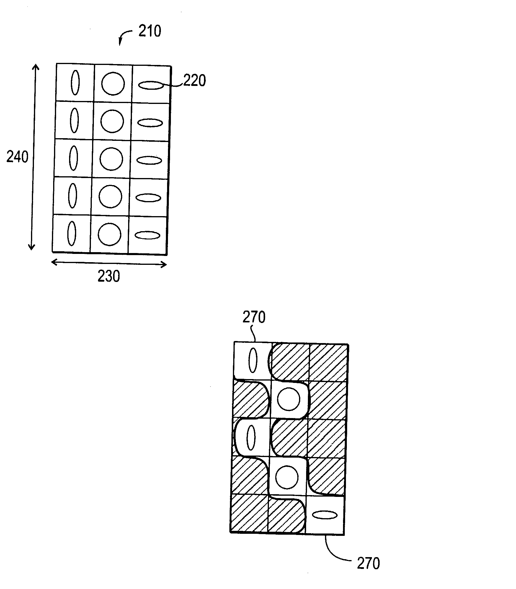
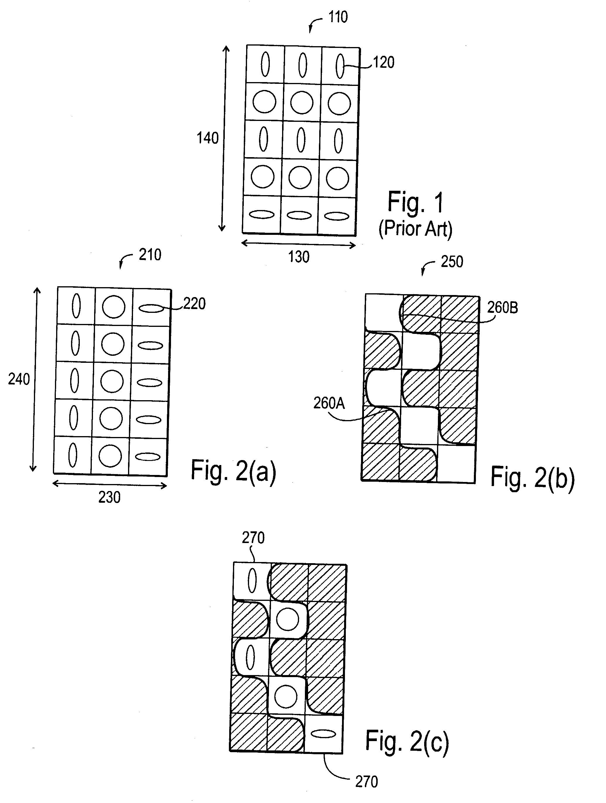
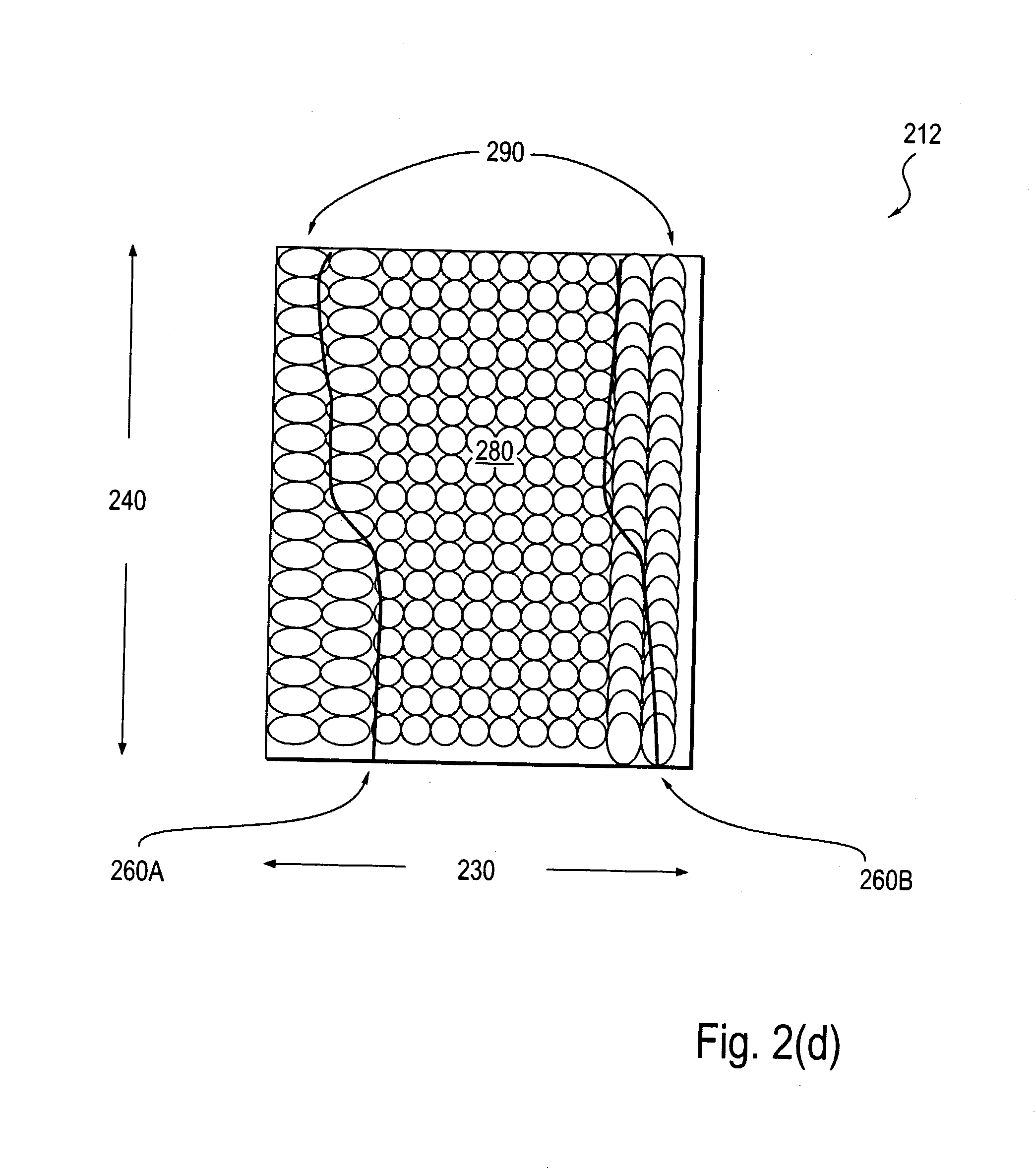
[0024] In the present invention, horizontal-vertical (H-V) bias along the direction of a slit is reduced by using an array 210, as shown in FIG. 2(a), in conjunction with an aperture 250 with articulated edges 260A and 260B, as shown in FIG. 2(b). H-V bias refers to CD variability between two orthogonal directions, in particular, the horizontal direction and the vertical direction. H-V bias varies as a function of pitch. Pitch is the periodicity in a pattern of regularly-repeating features. H-V bias may be caused by aberrations in the projection optics or non-uniformity in partial coherence of the illumination. One kind of optical aberration is astigmatism, which causes H-V bias that is very sensitive to focus. Another kind of optical aberration is coma, which causes H-V bias that is not appreciably sensitive to focus.
[0025] The array 210 is substantially planar with a first dimension 230 and a second dimension 240 that are orthogonal to each other. When a step-and-scan type of imag...
second embodiment
[0035] In the present invention, as shown in FIG. 3, a relay lens 310 is used to adjust partial coherence ellipticity across a field for the case of top hat illumination. A condenser 320 provides light energy input to the relay lens 310 by focusing Kohler illumination onto a first adjustable aperture 330. The light energy from the illuminator has a nominal partial coherence. The condenser 320 may be a microlens array, a fly's eye lens, a rod lens, or some other kind of optics.
[0036] The first adjustable aperture 330 defines field size. The first adjustable aperture 330 has articulated edges to locally adjust intensity or dose of the light energy as a function of Y or position along the slit. The adjustment may be made dynamically by software.
[0037] The relay lens 310 has a second adjustable aperture 340 at a Y-pupil plane. The second adjustable aperture 340 has edges that may be positioned to globally adjust the partial coherence in the Y-direction. The edges of the second adjustabl...
third embodiment
[0041] In the present invention, aberrations in an optical system are compensated by adjusting partial coherence in different directions at different pupil planes. For example, partial coherence may be adjusted in a first direction at a first pupil plane. Then partial coherence may be adjusted in a second direction at a second pupil plane. The second pupil plane is a conjugate of the image plane of the first direction.
[0042] The second direction may be orthogonal to the first direction. At each pupil plane, the partial coherence may be controlled globally or locally. Global control means that the adjustment of partial coherence is independent of position within the pupil plane. Local control means that the adjustment of partial coherence is a function of position within the pupil plane.
[0043] Controlling partial coherence in different directions at different pupil planes can maximize radiometric efficiency. In a photolithography process, controlling partial coherence in different di...
PUM
| Property | Measurement | Unit |
|---|---|---|
| light energy | aaaaa | aaaaa |
| size | aaaaa | aaaaa |
| dimension | aaaaa | aaaaa |
Abstract
Description
Claims
Application Information