
Method and apparatus for measurement of exit pupil telecentricity and source boresighting

a technology of telecentricity and source boresighting, applied in the field of semiconductor manufacturing, can solve the problem of positioning offset of box-in-box images, and achieve the effect of simple requirement of spatial uniformity

Inactive Publication Date: 2006-07-27
LITEL INSTR
View PDF8 Cites 1 Cited by
  • Summary
  • Abstract
  • Description
  • Claims
  • Application Information

AI Technical Summary

Benefits of technology

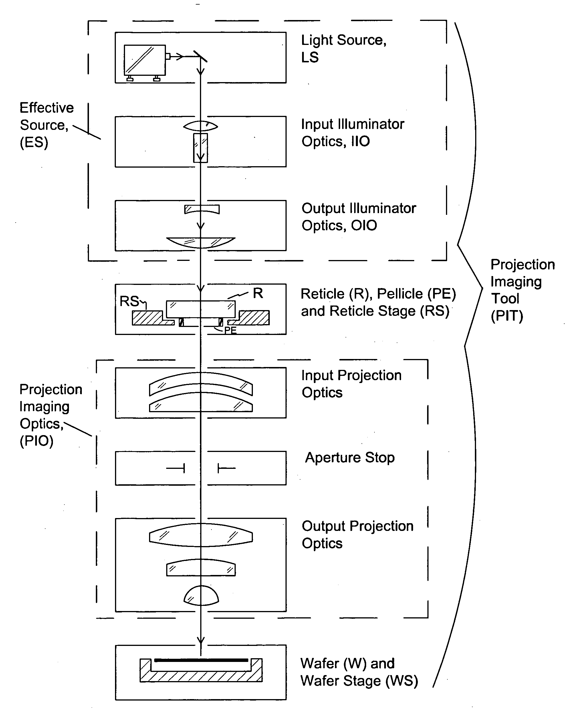
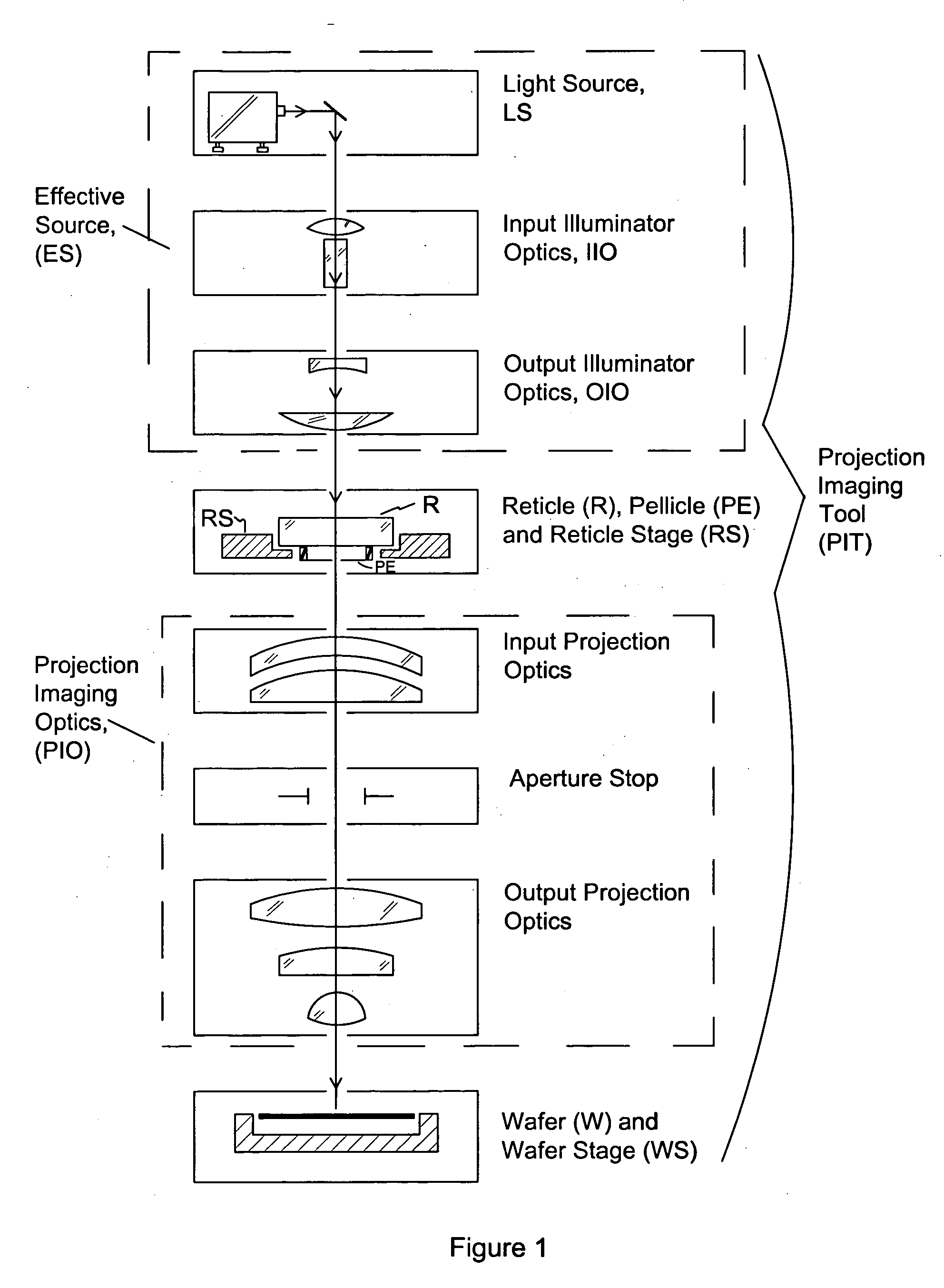
[0012] Photolithography plays the vital role in semiconductor manufacturing of defining the ultimate features that are etched or deposited within each layer of the device. Projection imaging machines, usually of the stepper or scanner variety, using effective light sources that can be varied over a wide range of configurations perform this function. FIG. 1 shows a block diagram of a typical projection imaging system as would be found in a stepper or scanner. Effective source, ES, is responsible for generating and shaping the light incident on the reticle. It consists of a light source, LS, (typically an excimer laser operatin...

Problems solved by technology

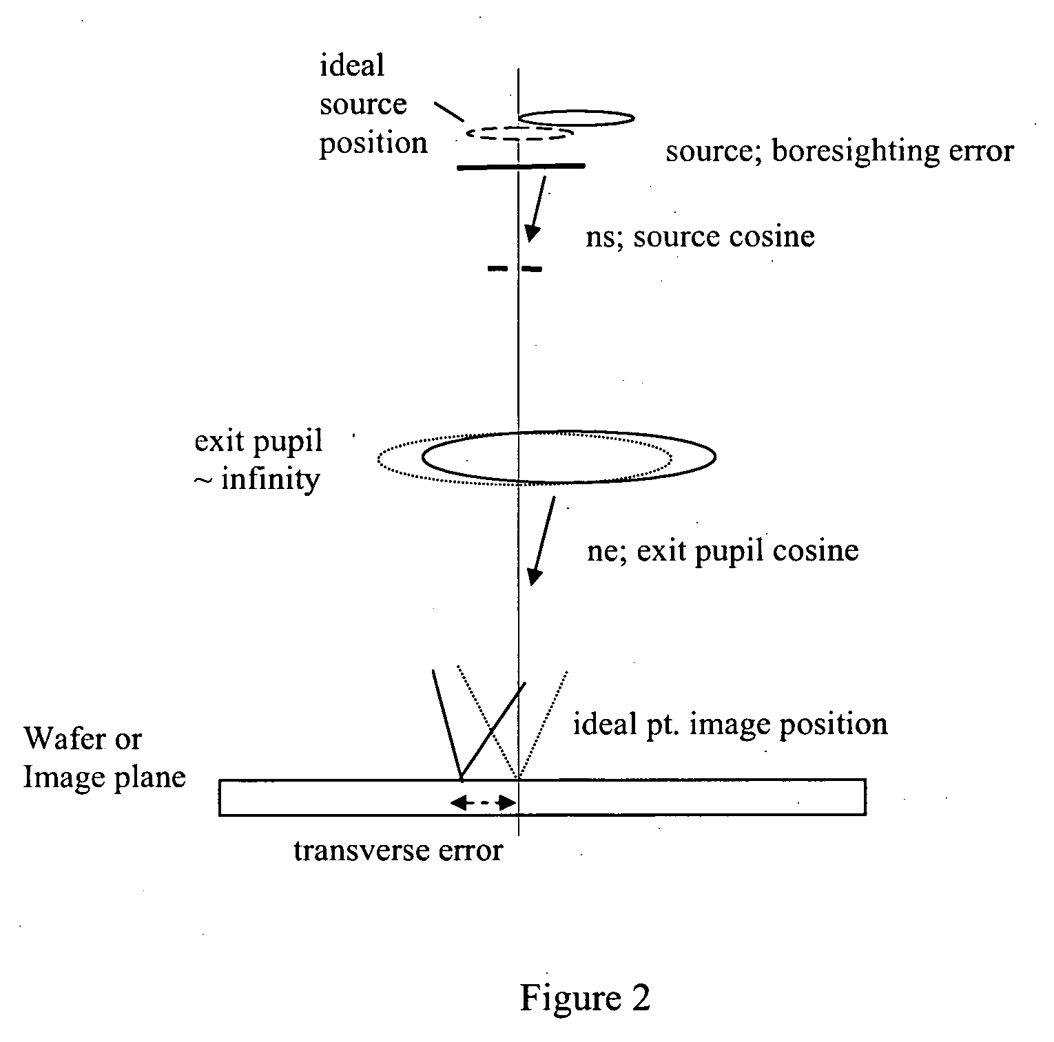
One problem that arises with this method is that a positional offset of the box-in-box image may be produced by other system effects besides the exit pupil telecentricity.

Method used


Image

  • Method and apparatus for measurement of exit pupil telecentricity and source boresighting
  • Method and apparatus for measurement of exit pupil telecentricity and source boresighting
  • Method and apparatus for measurement of exit pupil telecentricity and source boresighting

Examples


first embodiment

[0052]FIG. 3 shows a block diagram (Blocks 1-5) for a process used in a first embodiment.

Block 1: Provide Chrome Overlay Reticle

[0053] A chrome overlay reticle, or mask, is provided. FIG. 4a shows a sample of an encoded dark field reticle face with a 12×14 array of overlay groups (OLG). FIG. 4b shows a close-up of single overlay group (OLG) which in this case consists of an outer bar pattern (OB) slightly (Proc. of SPIE, Vol. CR52, pp. 160-188).

[0054] In one embodiment, a mask for determining telecentricity of an exit pupil in a projection imaging tool includes an array of patterns, each pattern having at least a first feature, a second feature, a third feature, and a fourth feature, wherein the first and second features are binary and at least a portion of the third and fourth are phase-shifting. In another embodiment, a mask for determining telecentricity of an exit pupil in a projection imaging tool includes an array of patterns, each pattern having at least a first feature a...

second embodiment

[0066] We now describe a method and apparatus for measurement of exit pupil telecentricity (divorced from the source boresighting error) using a reticle and diffuser. Refer to FIG. 9 for designation and description of the various blocks.

Block 8: Provide Reticle and Diffuser

[0067] Provide reticle with local diffuser on back side of reticle. The purpose is to provide a source with a sigma=σc>1. Where, ac is the critical sigma value where the contribution of the source to the box-in-box shift can be ignored, e.g., ⅆ2⁢xⅆzdns⁢〈〈ⅆ2⁢xⅆzdne·(Equation⁢ ⁢5)

[0068] To create this source setting we place or locate diffuser, D, (FIG. 10) on the reticle backside, RB (second surface). The diffuser, D, has an angular half-width / half angle (θd FIG. 10) big enough to spread out an incident source width σc to one with σeff≧σc. The effective source sigma of the combined diffuser / stepper source is σ⁢ ⁢eff=σ+M2⁢NA⁢ ⁢dNA

where NAd=sin(θd).

Since σeff≧σc we need for NAd: NA⁢ ⁢d≥2⁢(σc-σ)⁢NAM.

For exam...

third embodiment

[0070] For this additional embodiment we present a method for measuring exit pupil telecentricity independent from source boresighting error. A flowchart of this embodiment is shown in FIG. 12 where Blocks 1, 3, 4, and 5 are as described in the first embodiment.

Block 9: Set Source Sigma

[0071] The user provides effective source (ES) that is insensitive to source telecentricity on our particular pattern. That is: ⅆ2⁢xⅆzdns≅0(Equation⁢ ⁢6)

[0072] Some Exemplary Conditions for this Source Setting are:

TABLE 1MλNANAsNAoσs=NAsNANAoNAsd2⁢xdzdnsd2⁢xdzdne53650.60.5740.3850.9570.6700.002−1.10242480.80.7910.5300.9880.670−0.005−1.46842480.80.7190.4820.8990.850−0.006−1.650

Values in Table 1 are determined by lithographic simulation similar to those described above and shown in FIG. 6. The outer annular sigma while large (˜0.9), is still feasible on modern lithographic machines.

Blocks 3, 4, and 5: Print, Measure, and Reconstruct Exit Pupil Telecentricity

[0073] The process for these blocks ...


PUM


Abstract

Exit pupil and source telecentricity of a projection imaging tool system is determined. The system contains a light source, an optical imager, a reticle, a substrate, and a positioner. The light source is optically coupled to the optical imager, the optical imager having an exit pupil. The combination of the light source and the optical imager define a projection imaging tool, are characterized by a partial coherence. The reticle has an array of patterns, each pattern having at least a first feature and a second feature. A substrate may be used to record at least a first image and a second image of the features. The positioner is used to dispose the first image and the second image such that the first image has a first defocus and the second image has a second defocus different from the first defocus. A processor is used to calculate the telecentricity based on an exit pupil and light source differential shift coefficient and positional offsets between features contained in the first image and features contained in the second image.

Description

REFERENCE TO PRIORITY DOCUMENT [0001] This application claims priority benefit of U.S. Provisional Patent Application Ser. No. 60 / 647,615 filed Jan. 26, 2005 entitled “Method and Apparatus for Measurement of Exit Pupil Telecentricity and Source Boresighting” by Smith et al. Priority of the filing date of the prior application is hereby claimed, and the disclosure of the prior application is hereby incorporated by reference in its entirety.BACKGROUND [0002] 1. Field of the Invention [0003] The present invention relates generally to the field of semiconductor manufacturing and more specifically to the measurement of telecentricity of a projection imaging tool used in photolithography. [0004] 2. Description of Related Art [0005] Photolithography systems are commonly used in the manufacture of semiconductor devices. During fabrication, circuits are typically built one layer at a time by coating a substrate with a layer of photoresist and then exposing the photoresist to light transmitte...

Claims


Application Information

Patent Timeline
IPC IPC(8): G03B27/52
CPCG03F7/70191G03F7/70591G03F7/70616
Inventor SMITH, ADLAI H.HUNTER, ROBERT O. JR.
Owner LITEL INSTR
Learn More