Adiabatic polarization converter

a converter and adiabatic polarization technology, applied in the field ofadiabatic polarization converters, can solve the problems of extra components and/or costs, limiting the scope of their application,

Active Publication Date: 2010-09-07
INFINERA CORP
View PDF64 Cites 30 Cited by
  • Summary
  • Abstract
  • Description
  • Claims
  • Application Information

AI Technical Summary

Problems solved by technology

Therefore, it is sometimes necessary to convert or rotate the polarization state of a signal before it is inputted to a certain optical device.
While various devices exist for converting or rotating the polarization of optical signals, to Applicant's knowledge, these systems require additional and specialized materials, such for example magneto optic, gyrotropic, electrooptic, anisotropic or birefringent materials, which results in extra components and / or costs.
Further, some devices are wavelength dependent, introduce scattering loss, or are highly fabrication sensitive, thus limiting the scope of their application.

Method used


Image

  • Adiabatic polarization converter
  • Adiabatic polarization converter
  • Adiabatic polarization converter

Examples


example 1

Design / Performance

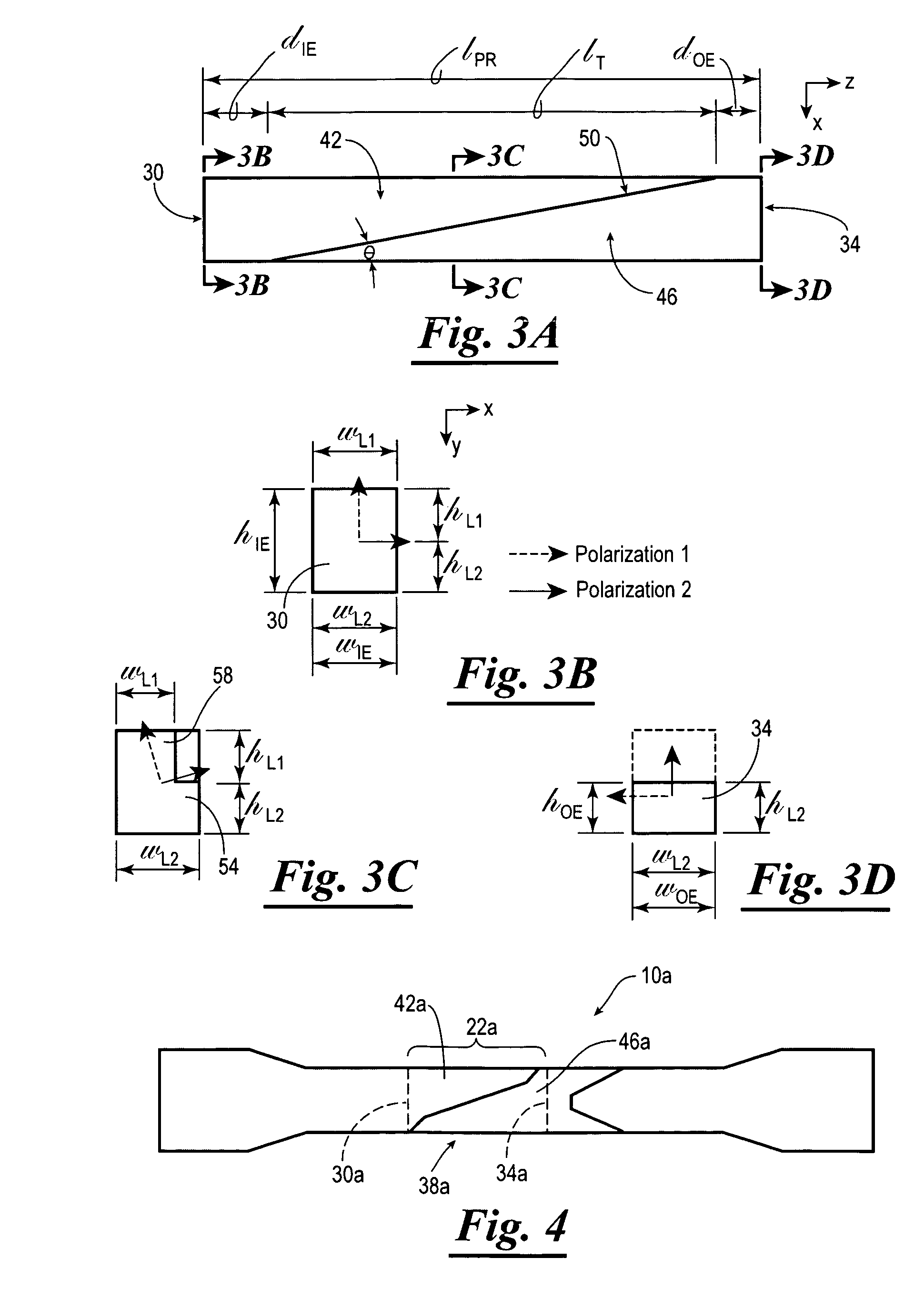
[0072]The polarization rotator 22 with a geometry as shown in FIG. 9 was numerically simulated using a full vector Beam Propagation Method (FV-BPM). The nominal waveguide thickness for the simulation was about 1.5 μm, and the polarization inducing etch depth was about 750 nm. The waveguide core index was about 1.70, while the cladding surrounding the waveguide index was about 1.45. The taper length IT was a design parameter that was varied.

[0073]Shown in FIGS. 10A and 10B are computational models for the X-polarized (TE) mode at the input end 30 of the polarization rotator 22, and shown in FIGS. 10C and 10D are the computational models for the Y-polarized (TM) modes at the input end 30 of the polarization rotator 22 (where the waveguide structure 10 is 1.1 μm wide and 1.5 μm thick). Shown in FIG. 11A is the optical field evolution for the X-polarized (TE) mode for the structure of FIG. 9 for a taper length of IT=500 μm, and shown in FIG. 11B is the optical field ev...

example 2

Application

[0076]As discussed herein, the waveguide structure 10 of the present invention can be used in an integrated optical circuit having other waveguide elements. As one example application, the waveguide structure 10 can be integrated with a polarization beam splitter, such as the polarization beam splitter described in a co-pending patent application entitled “Integrated Optical Polarization Beam Splitter”, which is identified by U.S. Ser. No. 10 / 661,891; the entire content of which is hereby expressly incorporated herein by reference.

[0077]For example, the polarization beam splitter can be utilized to split the polarization of an incident optical beam or signal into two orthogonal optical signals, a TE mode signal and a TM mode signal. One of the TE mode signal or the TM mode signal can then be transmitted through the polarization rotator 22 of the present invention so that its polarization is rotated to match the polarization of the other signal, thereby providing a single ...


PUM


Abstract

The present invention relates to a waveguide structure, and methods for making the same. The waveguide structure has a polarization rotator for rotating the polarization of the electromagnetic signal, preferably by about ninety-degrees. In one embodiment, the polarization rotator has a midsection with a first level and a second level. The first level of the midsection has a width that decreases along the length of the first level, while the second level has a substantially constant width along the length of the second level. Further, the waveguide structure can include an input conditioning section and the output conditioning section to facilitate matching between the polarization rotator and other waveguide elements.

Description

CROSS-REFERENCE TO RELATED APPLICATIONS[0001]Not applicable.STATEMENT REGARDING FEDERALLY SPONSORED RESEARCH OR DEVELOPMENT[0002]Not applicable.BACKGROUND OF THE INVENTION[0003]In general, a waveguide is a device, or a system of material boundaries, that is designed to confine and direct the propagation of electromagnetic waves, such as light or optical signals, along a length of the waveguide.[0004]An electromagnetic wave is a vector field that has two primary and orthogonal polarization states or vector directions associated with its propagation. These polarization states are generally referred to as the Transverse Electric (TE) mode and Transverse Magnetic (TM) mode for optical waveguides. In the TM mode, the magnetic lines of flux are predominantly oriented parallel to the substrate on which the waveguide sits, while in the TE mode the electric lines of flux are predominantly oriented parallel to the substrate.[0005]The performance of waveguides and other optical devices is ofte...

Claims


Application Information

Patent Timeline
Patent Type & Authority Patents(United States)
IPC IPC(8): G02B6/00G02B6/26
CPCG02B6/1228G02B6/126G02B6/2766
Inventor LITTLE, BRENT E.HRYNIEWICZ, JOHN
Owner INFINERA CORP
Why Eureka
Try Eureka