
Densely stacked and strain-compensated quantum dot active regions

a quantum dot active region, densely stacked technology, applied in the direction of active medium materials, lasers, semiconductor devices, etc., can solve the problems of low modal gain, low qd active region, drawbacks and disadvantages of conventional techniques

Inactive Publication Date: 2010-09-14
STC UNM
View PDF7 Cites 33 Cited by
  • Summary
  • Abstract
  • Description
  • Claims
  • Application Information

AI Technical Summary

Problems solved by technology

Problems arise for the QD active region due to its very low modal gain at the ground state energy level.
However, this conventional technique has drawbacks and disadvantages.
For example, one drawback is caused by the vertically propagating strain field that originates at the first QD active region and grows with each subsequent QD active region.
Although such strain field is the cause of the columnar growth mode characteristic for all strain-coupled QD active regions, the strain energy in the strain field eventually grows too large to be absorbed by the QD formation.
The strain energy may then drive defect formation such as coalescence of QDs, thus limiting the number of stacks.
However, this solution also has drawbacks and disadvantages.

Method used


Image

  • Densely stacked and strain-compensated quantum dot active regions
  • Densely stacked and strain-compensated quantum dot active regions
  • Densely stacked and strain-compensated quantum dot active regions

Examples


Embodiment Construction

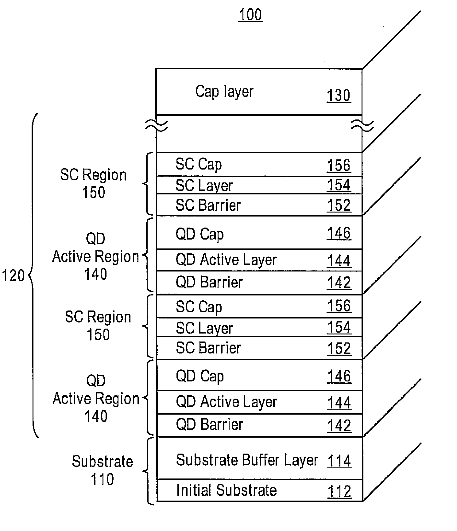
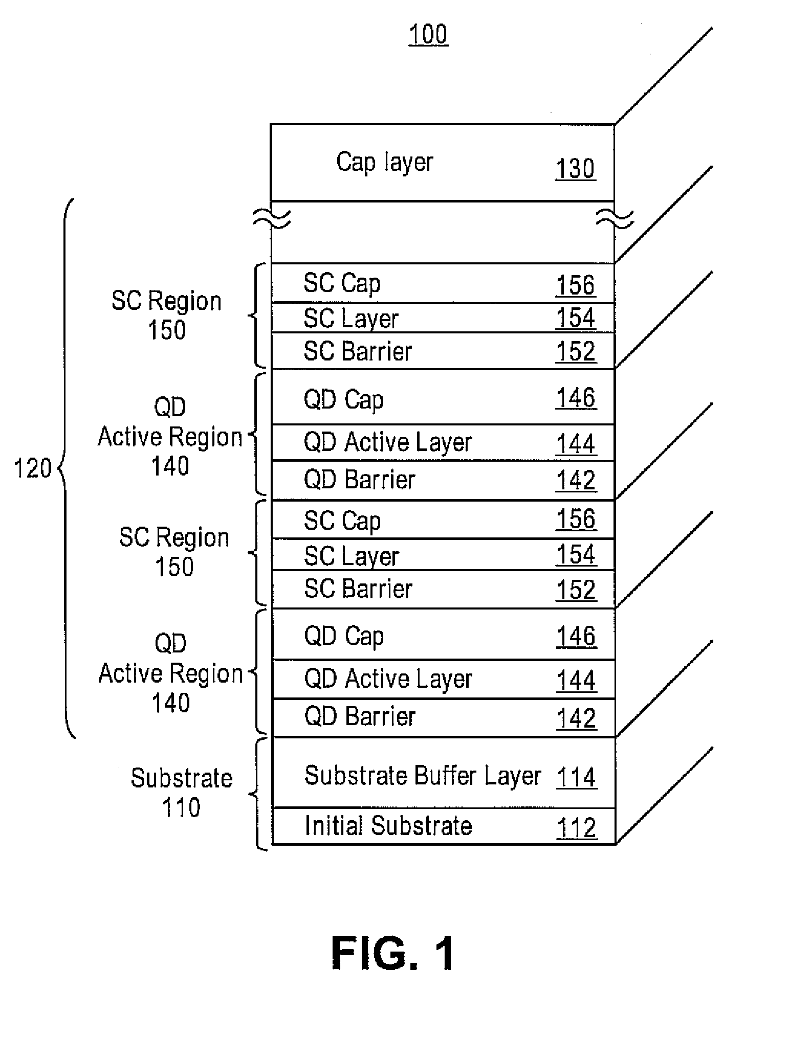
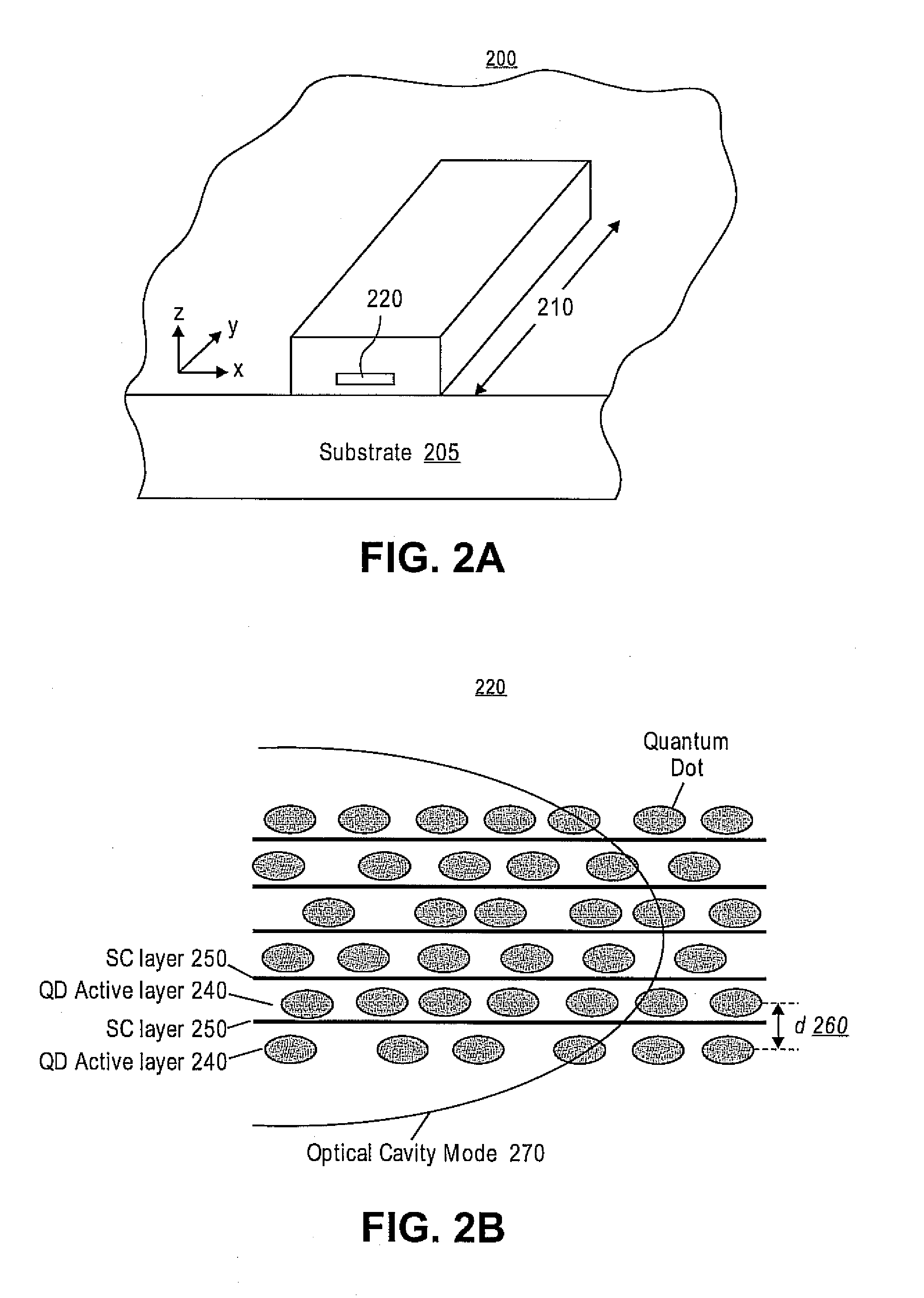
[0019]Embodiments provide a QD active structure and a methodology for forming the QD active structure with densely-stacked and strain-compensated QD active regions. More specifically, strain-compensation (SC) regions may be formed to alternate with the QD active regions to eliminate the compressive strain of each QD active region. An SC region may include an SC layer, which may be a tensile layer used for counterbalancing the strain of an adjacent QD active region. Thus, the SC layer may allow desired stacking of the QD active regions while still realizing closely spaced QD layers, and resulting in a increased modal gain for the QD active region.

[0020]Reference will now be made in detail to exemplary embodiments of the invention, an example of which is illustrated in the accompanying drawings. Wherever possible, the same reference numbers will be used throughout the drawings to refer to the same or like parts.

[0021]In the following description, reference is made to the accompanying ...


PUM


Abstract

Embodiments provide a quantum dot active structure and a methodology for its fabrication. The quantum dot active structure includes a substrate, a plurality of alternating regions of a quantum dot active region and a strain-compensation region, and a cap layer. The strain-compensation region is formed to eliminate the compressive strain of an adjacent quantum dot active region, thus allowing quantum dot active regions to be densely-stacked. The densely-stacked quantum dot active region provides increased optical modal gain for semiconductor light emitting devices such as edge emitting lasers, vertical cavity lasers, detectors, micro-cavity emitters, optical amplifiers or modulators.

Description

RELATED APPLICATIONS[0001]This application claims priority from U.S. Provisional Patent Application Ser. No. 60 / 705,494, filed Aug. 5, 2005, which is hereby incorporated by reference in its entirety.GOVERNMENT RIGHTS[0002]This invention was made with government support under Contract No. F49620-03-1-0433 awarded by the Air Force Office of Scientific Research. The government has certain rights in the invention.FIELD OF THE INVENTION[0003]This invention relates generally to quantum dot active structures used in semiconductor light emitting devices, and, more particularly, to quantum dot active structures with densely-stacked and strain-compensated quantum dot active regions.BACKGROUND OF THE INVENTION[0004]Quantum dots (QDs) continue to intrigue technologists with the potential benefits of zero-dimensionality, low threshold current density and temperature sensitivity in modern semiconductor laser applications. The QDs formed by strain-driven processes are especially interesting since ...

Claims


Application Information

Patent Timeline
Patent Type & Authority Patents(United States)
IPC IPC(8): H01L29/66
CPCB82Y20/00H01S5/34
Inventor HUFFAKER, DIANA L.NUNTAWONG, NOPPADON
Owner STC UNM
Learn More