Load condition controlled power strip

a power strip and condition control technology, applied in the integration of power network operation systems, emergency power supply arrangements, relays, etc., can solve the problems of increasing the number of power loss, increasing the number of connected devices left on, and often going into self-imposed idle modes. , to achieve the effect of reducing or eliminating power, reducing the power consumption of the power strip, and facilitating the disengagement of the primary circui

Inactive Publication Date: 2010-09-14
IGO INC
View PDF87 Cites 41 Cited by
  • Summary
  • Abstract
  • Description
  • Claims
  • Application Information

AI Technical Summary

Benefits of technology

[0005]In accordance with various aspects of the present invention, a method and circuit for reducing power consumption of a power strip during idle conditions is provided. In an exemplary embodiment, a power strip is configured for reducing or eliminating power during idle mode by disengaging at least one outlet from a power input. A power strip may include one or more outlets and one or more outlet circuits, with AC power input connected to the outlets through the outlet circuit(s). The outlet circuit may include a current transformer, a control circuit, and a switch. The secondary winding of the current transformer provides an output power level signal that is proportional to the load at the outlet. In an exemplary embodiment, if behavior of the secondary winding of the current transformer indicates that at least one outlet is drawing substantially no power from the AC power input, the switch facilitates disengaging of the primary circuit of the current transformer from such outlet.

Problems solved by technology

Even with a power adapter which conforms to the regulatory requirement of dissipating less then 0.5 watts / hour, this extended idle time adds up to 3000 watt hours of wasted energy each year per adapter.
When calculating the wasted energy of the numerous idle power adapters, the power lost is considerable.
When not in use, these connected devices will often be left on and go into self-imposed idle modes that typically consume less than 1 watt per device.

Method used


Image

  • Load condition controlled power strip
  • Load condition controlled power strip
  • Load condition controlled power strip

Examples


Embodiment Construction

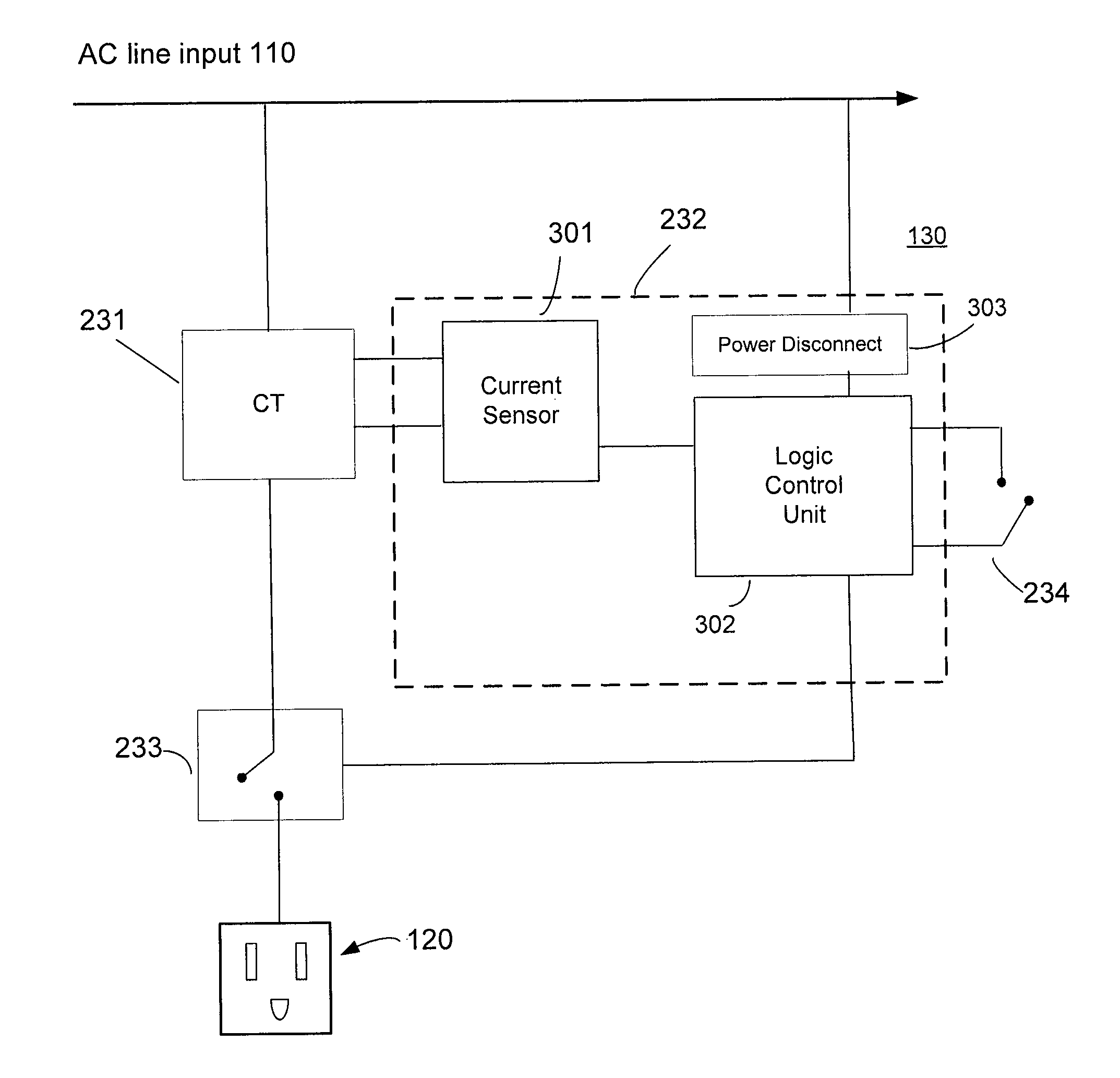
[0013]The present invention may be described herein in terms of various functional components and various processing steps. It should be appreciated that such functional components may be realized by any number of hardware or structural components configured to perform the specified functions. For example, the present invention may employ various integrated components, such as buffers, current mirrors, and logic devices comprised of various electrical devices, e.g., resistors, transistors, capacitors, diodes and the like, whose values may be suitably configured for various intended purposes. In addition, the present invention may be practiced in any integrated circuit application. However for purposes of illustration only, exemplary embodiments of the present invention will be described herein in connection with a sensing and control system and method for use with power strip circuits. Further, it should be noted that while various components may be suitably coupled or connected to ...


PUM


Abstract

In accordance with various aspects of the present invention, a method and circuit for reducing power consumption of a power strip is provided. In an exemplary embodiment, a power strip is configured for reducing or eliminating power during idle mode by disengaging an outlet from power input. A power strip may include two or more outlets and two or more outlet circuits, with AC power input connected to the outlets through the outlet circuit(s), which may include a current transformer, a control circuit, and a switch. The current transformer secondary winding provides an output power level signal proportional to the outlet load. If behavior of the current transformer secondary winding indicates that the outlet is drawing substantially no power from the AC power input, the switch facilitates disengaging of the current transformer primary from the outlet.

Description

CROSS-REFERENCE TO RELATED APPLICATIONS[0001]This application claims priority to and benefit of U.S. Provisional Application No. 61 / 076,527, filed Jun. 6, 2008, and entitled “LOAD CONDITION CONTROLLED POWER STRIP”, and hereby incorporated by reference.FIELD OF INVENTION[0002]The present invention relates to reducing power consumption in electronic devices. More particularly, the present invention relates to a circuit and method for disengaging an outlet in a power strip from a power input when idle load conditions are present.BACKGROUND OF THE INVENTION[0003]The increasing demand for lower power consumption and environmentally friendly consumer devices has resulted in interest in power supply circuits with “green” technology. For example, on average, a notebook power adapter continuously “plugged in” spends 67% of its time in idle mode. Even with a power adapter which conforms to the regulatory requirement of dissipating less then 0.5 watts / hour, this extended idle time adds up to 3...

Claims


Application Information

Patent Timeline
Patent Type & Authority Patents(United States)
IPC IPC(8): H01H3/42
CPCH02J9/005Y02B70/30Y04S20/20
Inventor DUBOSE, RICHARD G.THORNTON, WALTERHEIL, MICHAEL D.
Owner IGO INC
Why Eureka
Try Eureka