Phase detector for half-rate bang-bang CDR circuit

a phase detector and clock-based technology, applied in the field of phase detectors, can solve the problems of unfavorable clock signal output, serious challenge, glitches, etc., and achieve the effects of preventing glitches, preventing jitters, and reducing components

Inactive Publication Date: 2010-09-14
FARADAY TECH CORP
View PDF1 Cites 7 Cited by
  • Summary
  • Abstract
  • Description
  • Claims
  • Application Information

AI Technical Summary

Benefits of technology

[0009]Accordingly, the present invention is directed to a phase detector, for effectively eliminating the generation of the glitch, and thus preventing glitters.
[0010]The present invention is directed to a phase detector, which uses simplified components, so as to save layout area, and reduce layout complexity in considering symmetrical layout.
[0019]The first above-mentioned phase detector introduces an additional delay before outputting the comparison values as the first instruction signal and the second instruction signal, to provides a solution about the glitch of the conventional phase detector, thus preventing jitters. The second above-mentioned phase detector employs DETFFs as main components, which not only prevents glitches, but also uses less components than the first above-mentioned phase detector, saves layout area, and simplifies the winding complexity when considering the layout symmetry.

Problems solved by technology

However, when operating with a very high transmitting bit rate, e.g., 5 GHz, it is a serious challenge to design an oscillator adapted for an adjustment range thereof with a reasonable jitter condition.
This glitch is undesired, because it often causes ripples generated with a control voltage of the VCO, and therefore causes glitters of the frequency and phase of outputted clock signals.

Method used


Image

  • Phase detector for half-rate bang-bang CDR circuit
  • Phase detector for half-rate bang-bang CDR circuit
  • Phase detector for half-rate bang-bang CDR circuit

Examples


Embodiment Construction

[0030]Reference will now be made in detail to the present preferred embodiments of the invention, examples of which are illustrated in the accompanying drawings. Wherever possible, the same reference numbers are used in the drawings and the description to refer to the same or like parts.

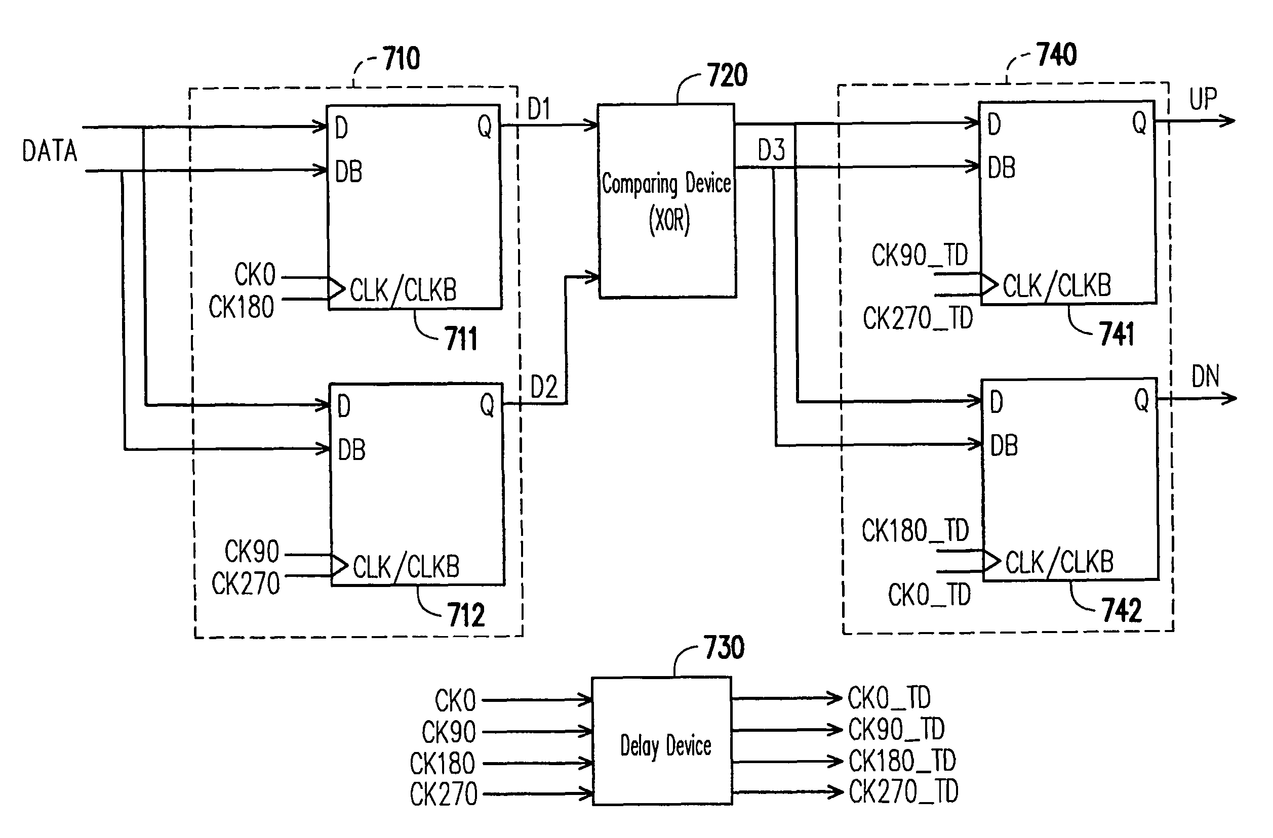
[0031]FIG. 4 is a block diagram illustrating a phase detector for a half-rate bang-bang CDR circuit according to an embodiment of the present invention. The phase detector includes a sampling device 410, a comparing device 420, and an output device 430. The comparing device 420 is coupled to the sampling device 410. The output device 430 is coupled to the comparing device 420. The sampling device 410 samples a data signal DATA according to four clock signals, CK0, CK90, CK180, and CK270, so as to provide four corresponding sampling values D0, D90, D180, and D270. The clock signals CK0, CK90, CK180, and CK270 have the same frequency and different phases. There is a 90 degree phase difference between e...


PUM


Abstract

A phase detector, including a sampling device, a comparing device, and an output device, is provided. The sampling device samples a data signal according to a plurality of clock signals, so as to provide a plurality of corresponding sampling values. The clock signals have the same frequency and different phases. The comparing device is coupled to the sampling device, and provides a plurality of corresponding comparison values according to comparison results of each of the sampling values comparing with the next sampling value. The output device is coupled to the comparing device, and outputs two of the comparison values in response to edges of the clock signals. The two outputted comparison values serve as a first instruction signal and a second instruction signal respectively. The first and the second instruction signals are referred to in controlling the frequency and the phase of the foregoing clock signals.

Description

BACKGROUND OF THE INVENTION[0001]1. Field of the Invention[0002]The present invention generally relates to a phase detector, and more particularly, to a phase detector for a half-rate bang-bang clock and data recovery (CDR) circuit.[0003]2. Description of Related Art[0004]Because of the popularization and development of the communication technology, data are now transmitted with a higher bit rate than ever before. However, when operating with a very high transmitting bit rate, e.g., 5 GHz, it is a serious challenge to design an oscillator adapted for an adjustment range thereof with a reasonable jitter condition. Accordingly, a half-rate CDR technology is developed in response to such a challenge. According to the half-rate CDR technology, when tracking a data signal, a voltage control oscillator (VCO) is required to generate a clock signal which frequency is equal to a half of a bit rate of the data transmitted thereby.[0005]In a thesis, “A 9-16 Gb / s Clock and Data Recovery Circuit...

Claims


Application Information

Patent Timeline
Patent Type & Authority Patents(United States)
IPC IPC(8): G01R25/00H03D13/00
CPCH03L7/089H03L7/091H04L7/033
Inventor TSENG, YU-HSINHSIUNG, WEN-CHING
Owner FARADAY TECH CORP
Why Eureka
Try Eureka