Image displaying apparatus

a technology for displaying apparatuses and images, applied in the direction of electrical apparatus casings/cabinets/drawers, television systems, instruments, etc., to achieve the effect of superior effect and increase the area of the panel modul

Active Publication Date: 2010-09-14
MAXELL HLDG LTD
View PDF41 Cites 12 Cited by
  • Summary
  • Abstract
  • Description
  • Claims
  • Application Information

AI Technical Summary

Benefits of technology

[0016]With such the present invention as was mentioned above, while dissolving the problems accompanying with an increase of the area of panel module due to the large-sizing of the image displaying apparatus, there can be achieved superior effects, i.e., enabling to manufacture a panel module, being superior in the mechanical strength thereof, easily and cheaply, and thereby providing an image displaying apparatus suitable for the large-sizing and / or thin-sizing of the apparatus.
[0020]As was mentioned above, with such the present invention as was mentioned above, while dissolving the problems accompanying with an increase of the area of panel module due to the large-sizing of the image displaying apparatus, there can be achieved superior effects, i.e., enabling to provide the supporting structures of the image displaying apparatus, being suitable for the thin-sizing of the apparatus, including the structures for attaching the power source board and the driver circuit board, etc., on the reverse surface of the said panel module.

Problems solved by technology

However, such the conventional arts as was mentioned above, in particular, the structures of providing such the “X”-like shaped supporting member, as is shown in the Patent Document 5 mentioned above, brings about a problem within thin-sizing of the image displaying apparatus, and therefore, it cannot to be said that, necessarily, it is the supporting structures suitable for the practical use.

Method used


Image

  • Image displaying apparatus
  • Image displaying apparatus
  • Image displaying apparatus

Examples


Embodiment Construction

[0029]Hereinafter, embodiments according to the present invention will be fully explained by referring to the attached drawings. However, the present embodiment relates an image displaying apparatus applying a liquid crystal display (LCD) therein, and hereinafter, explanation will be made on the image displaying apparatus applying this liquid crystal display therein, together with supporting structures thereof.

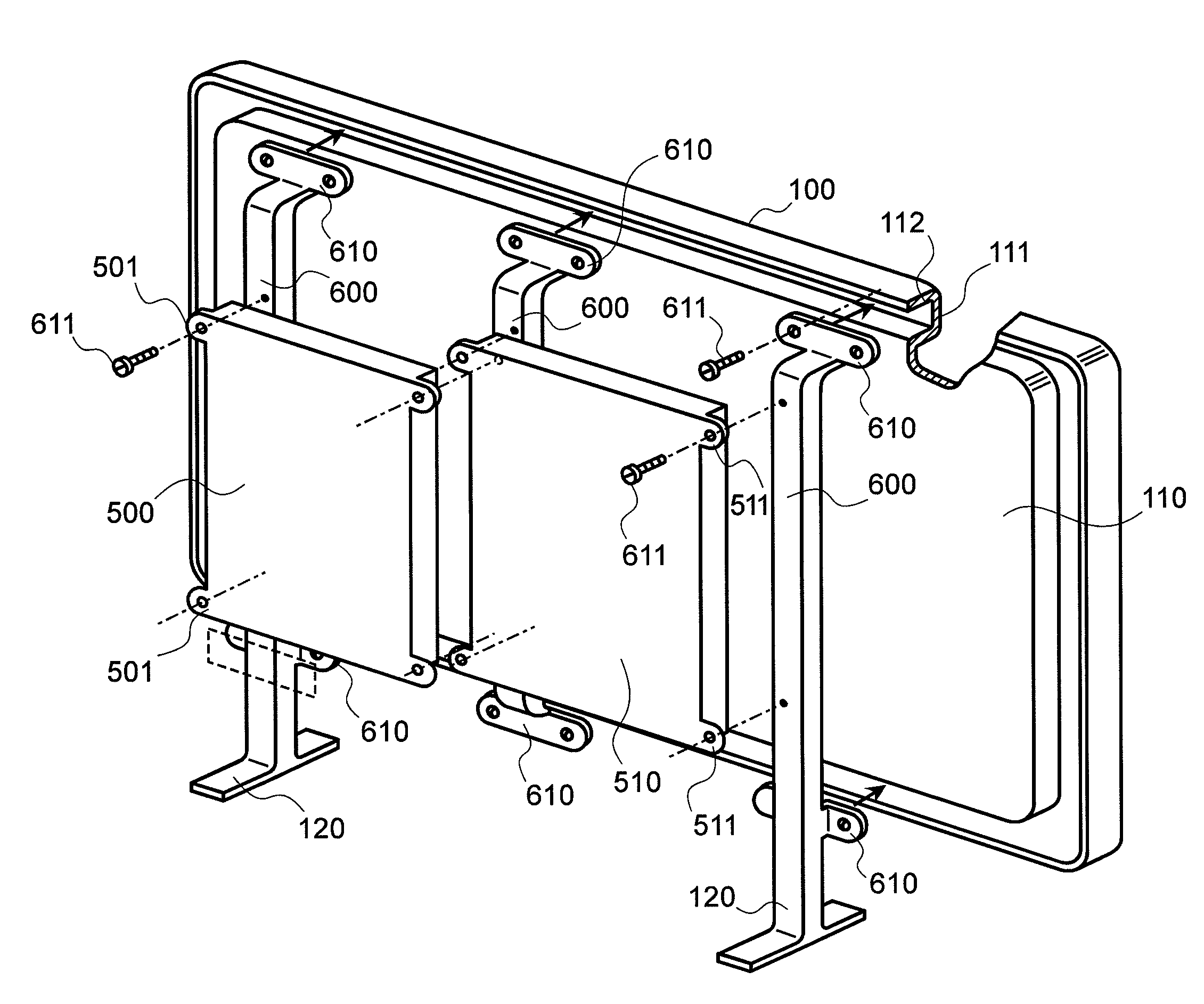
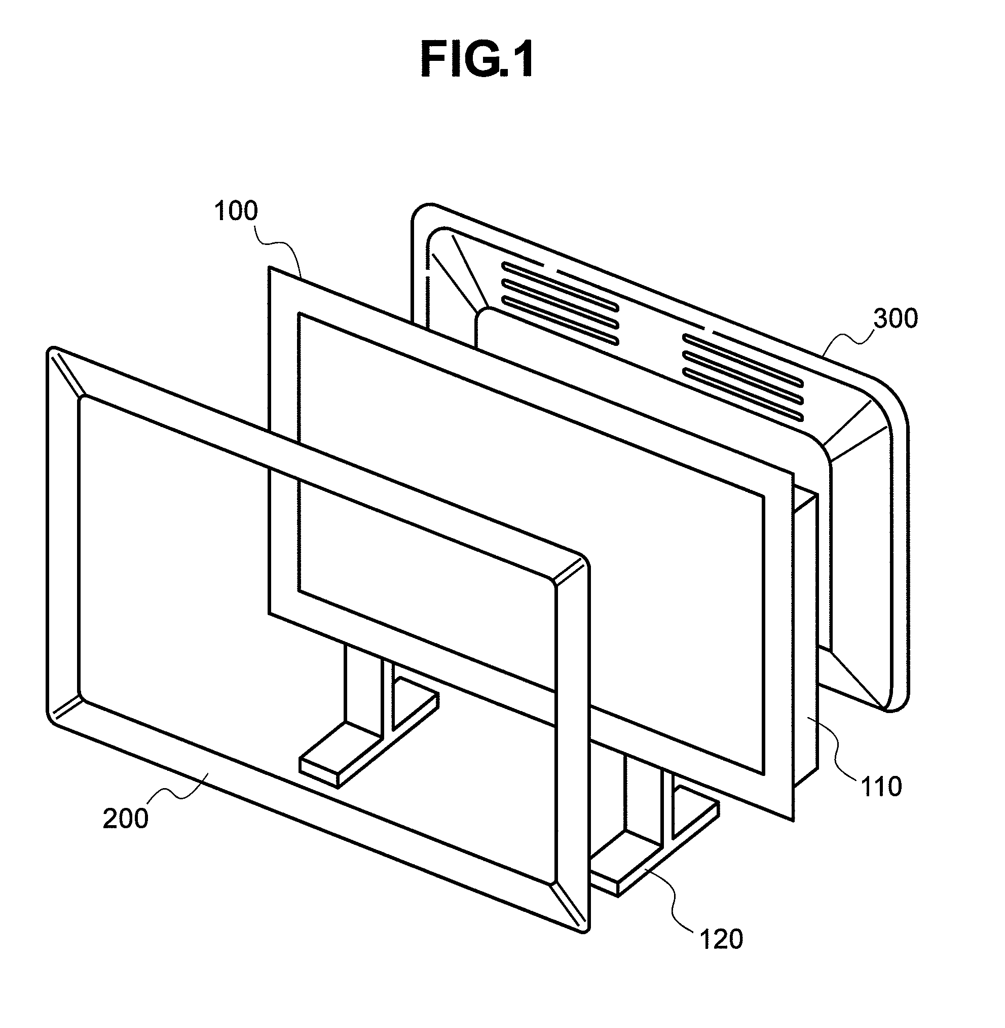
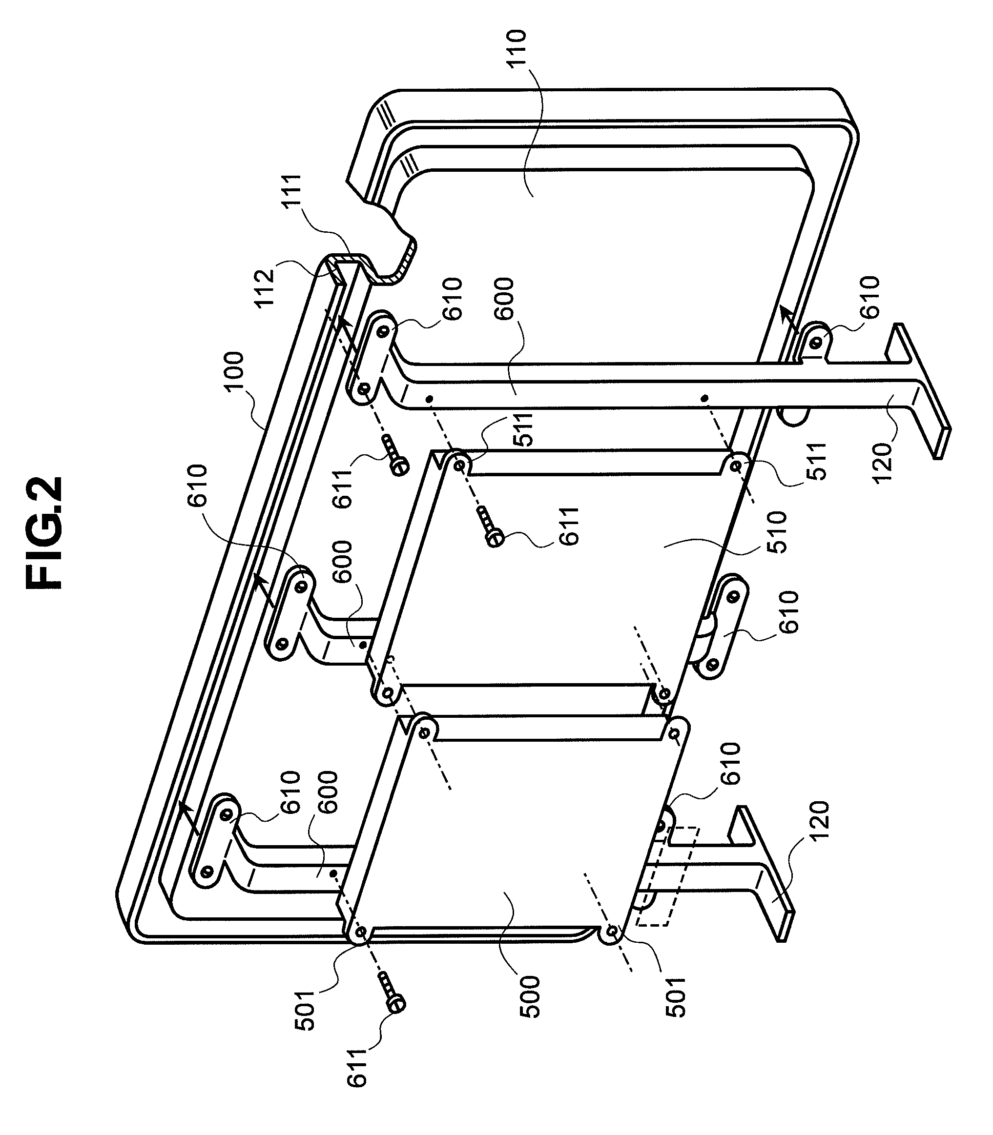
[0030]First of all, FIG. 1 attached herewith shows the entire structures of the image displaying apparatus, according to the present invention, in the expansion manner thereof, and in this figure, a reference numeral 100 depicts a liquid crystal display (LCD), as the large-size image displaying apparatus. Further, normally, this liquid crystal display (LCD) is attached on an opening side of a frame 110, being made from a thin aluminum plate, for example, which is formed into a box-like shape having an about “U”-like cross-section, and being shallow up to the bottom thereof and...


PUM

PropertyMeasurementUnit
sizeaaaaaaaaaa
semi-circular shapeaaaaaaaaaa
shapeaaaaaaaaaa

Abstract

An image displaying apparatus including the housing, and a panel module, having a frame of a rectangular shape in an outer configuration thereof, and a display panel with a display surface which is mounted on the frame, and being attached on the housing. The frame includes a flange portion formed along an outer periphery of the frame and extending in a direction substantially parallel to the display surface of the display panel. The flange portion is provided with a reinforcement portion extending along substantially an entirety of an outer periphery of the flange portion of the frame.

Description

BACKGROUND OF THE INVENTION[0001]The present invention relates to a large-size image displaying apparatus applying therein, such as, a liquid crystal display (LCD) or a plasma display (PDL), for example, and it relates, in particular, to supporting structures of a panel module for building up the large-size image displaying apparatus.[0002]In recent years, accompanying with digitalizing and / or high definition of the television broadcasting, a demand is made for a large-size and thin-type image displaying apparatus for receiving the television broadcasting on the air, i.e., a television receiver, and as such the image displaying apparatus for satisfying such demand, as well as, the conventional projection-type displaying apparatus, those also appear widely on the market, adapting the liquid crystal display (LCD) and the plasma display (PDL) therein. And, including the structures of external appearance of the apparatus of, such the large-size and thin-type image displaying apparatus, ...

Claims


Application Information

Patent Timeline
Patent Type & Authority Patents(United States)
IPC IPC(8): G02F1/1333
CPCH05K5/0217H04N5/64H05K5/0017
Inventor HIRADATE, MIKAYAMADA, HIDEMIKAKU, NOBUYUKI
Owner MAXELL HLDG LTD
Why Eureka
Try Eureka