
Formation and rotational apparatus for cylindrical workpieces

a technology of rotational apparatus and cylindrical workpiece, which is applied in the direction of metal working apparatus, other manufacturing equipment/tools, manufacturing tools, etc., can solve the problems of diameter elbow workpieces, slightly non-uniform elbow formation,

Active Publication Date: 2010-09-21
FORMTEK
View PDF30 Cites 9 Cited by
  • Summary
  • Abstract
  • Description
  • Claims
  • Application Information

AI Technical Summary

Benefits of technology

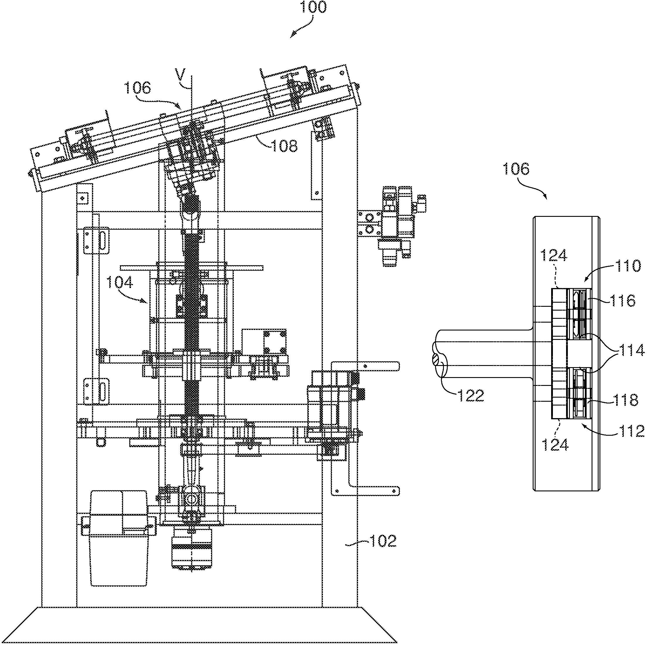
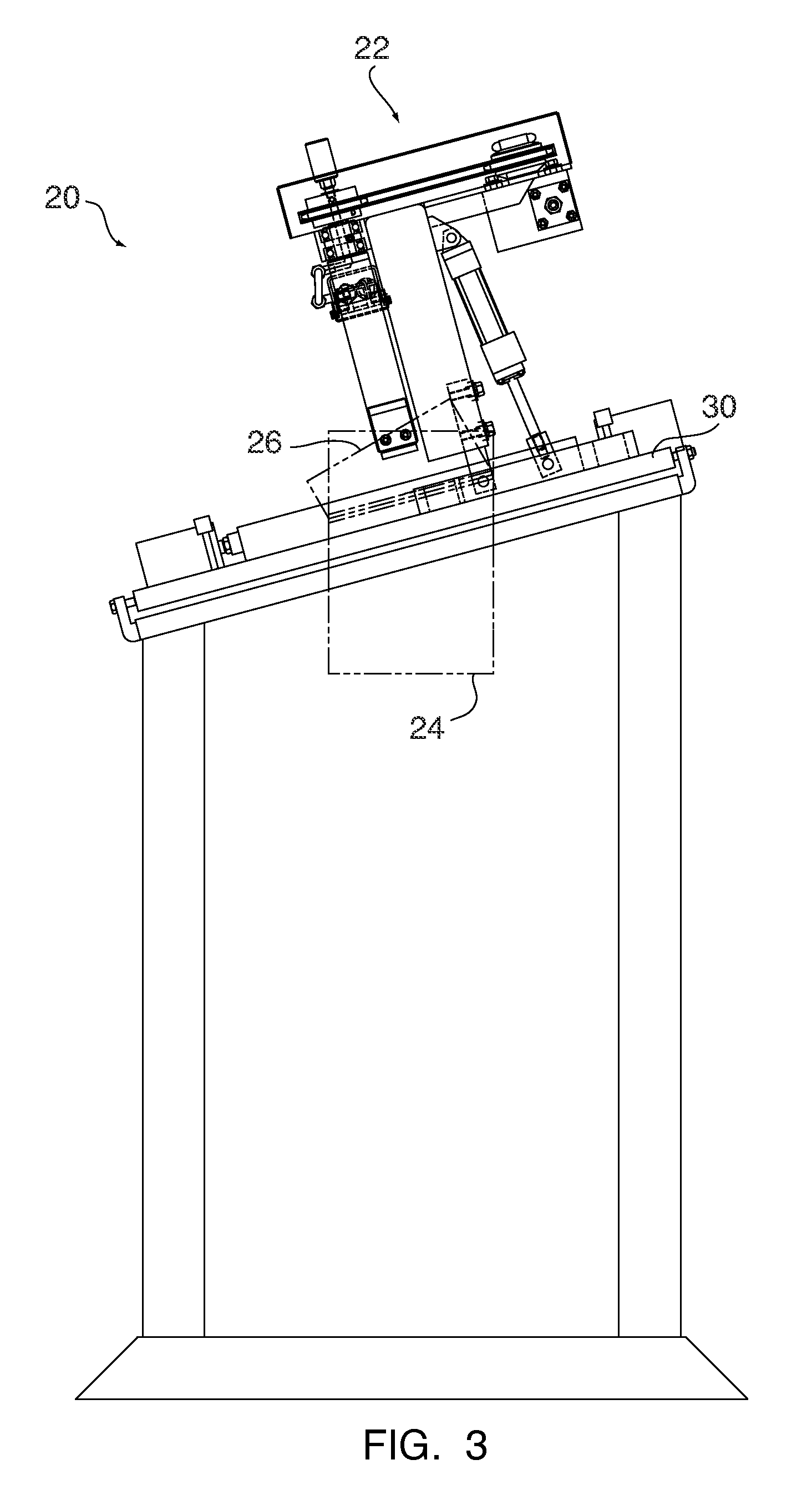
"The present invention provides an elbow rotator that can automatically turn each section of an elbow duct to their proper orientations. It can be incorporated into an elbow formation apparatus or used as a standalone apparatus. The elbow rotator can simultaneously rotate each integrally formed section of an elbow workpiece. The invention also provides a dual head elbow rotator apparatus that can balance the forces incident upon the elbow workpieces during formation. The apparatus includes a frame and a head with two slots and an armature with a cutting wheel and a beading wheel for successively forming each of the interconnected sections. A gripping mechanism is operatively connected to the armature, and a drive mechanism selectively rotates the armature about the axis of rotation after the gripping means has closed about one of the interconnected sections."

Problems solved by technology

While the known hand manipulation of elbow workpieces is effective to a certain degree, such a process is manually difficult and time consuming, as well as oftentimes resulting in the formation of finished elbows having slightly non-uniform characteristics.
Additional complications arise when large diameter elbow workpieces are utilized.

Method used


Image

  • Formation and rotational apparatus for cylindrical workpieces
  • Formation and rotational apparatus for cylindrical workpieces
  • Formation and rotational apparatus for cylindrical workpieces

Examples


Embodiment Construction

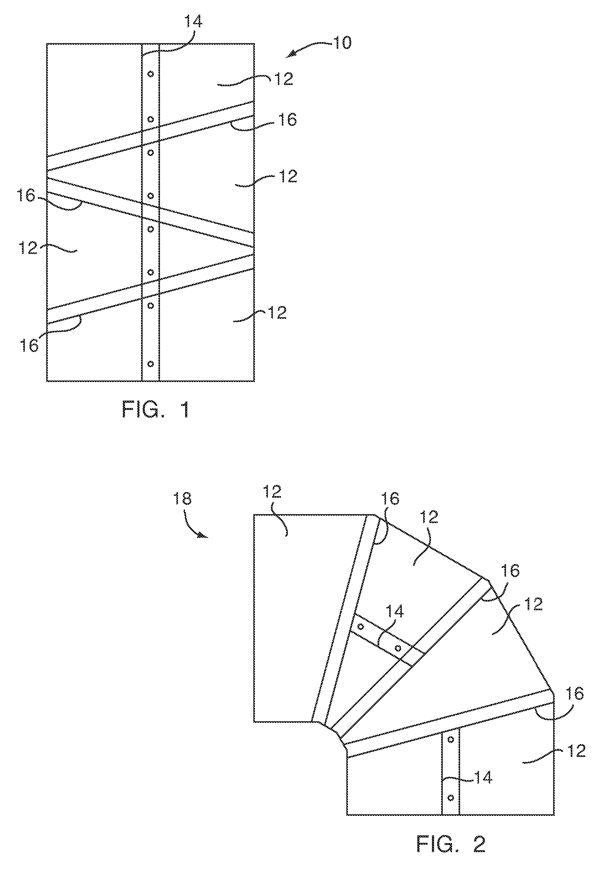
[0034]FIG. 1 illustrates a section of an elbow ductwork 10 prior to the elbow 10 being rotated into its final form. As can be seen in FIG. 1, the elbow 10 includes several sections 12 that have been formed by bending a sheet-metal workpiece, or the like, into a cylindrical shape about a common seam 14. Each of the sections 12 are separated from one another by an elbow joint 16 which has been cut and formed in the elbow 10 in a manner well known in the art. As will be appreciated, each of the section 12 of the elbow 10 shown in FIG. 1 must be turned with respect to one another in order to form the finished elbow 18, shown in FIG. 2.

[0035]As illustrated in FIG. 2, and in contrast to the elbow workpiece shown in FIG. 1, the seam 14 is no longer continuous along the length of the finished elbow 18 due to the individual rotation of the sections 12. During rotation, it is typical that each of the sections 12 experience an approximately 180° rotation with respect to adjacent sections in or...


PUM

PropertyMeasurementUnit
rotationaaaaaaaaaa
anglesaaaaaaaaaa
diameteraaaaaaaaaa

Abstract

A formation and rotation apparatus for use in forming and rotating interconnected sections of a cylindrical workpiece, including a frame and a head arranged within the frame, the head defining two slots and being operatively rotated via an integral drive assembly. A first slide block is slidably disposed within one of the two slots, and a second slide block is disposed within another of the two slots, each of the first and the second slide blocks include a cutting wheel and a beading wheel for successively forming each of the interconnected sections. An armature having an axis of rotation is also provided, along with a gripping mechanism being operatively connected to the armature. A drive mechanism selectively rotates the armature about the axis of rotation after the gripping means has closed about one of the interconnected sections.

Description

CROSS REFERENCE TO RELATED APPLICATIONS[0001]This application claims the benefit of U.S. Provisional Application Ser. No. 60 / 691,713, filed on Jun. 17, 2005, herein incorporated by reference in its entirety.FIELD OF THE INVENTION[0002]This invention relates, in general, to a formation and rotation apparatus for use in forming and rotating interconnected sections of a cylindrical workpiece, and deals more particular with a formation and rotation apparatus that will automatically form and turn each section of cylindrical workpiece to its proper orientation even in the cases of large diameter elbow workpieces.BACKGROUND OF THE INVENTION[0003]Elbow sections of ductwork are typically formed as straight pieces of cylindrical ductwork prior to being manipulated into a finished elbow having a substantial bend attributed thereto. This manipulation has traditionally been accomplished by hand.[0004]While the known hand manipulation of elbow workpieces is effective to a certain degree, such a p...

Claims


Application Information

Patent Timeline
Patent Type & Authority Patents(United States)
IPC IPC(8): B23P11/00B21D39/00
CPCB21C37/125B21C37/28Y10T29/5191Y10T29/5143Y10T29/49444Y10T29/53435B25J11/00
Inventor RIECK, LELAND M.
Owner FORMTEK
Learn More