Weight compensation device for a lifting door

a technology for lifting doors and weight compensation, which is applied in door/window protective devices, wing accessories, shutters/movable grilles, etc., can solve the problems of increased wear of torsion springs, limited service life, and considerable dynamic tension peaks of torsion springs, etc., and achieves long service life and small number of components. , the effect of unsusceptible to wear

Active Publication Date: 2010-09-21
EFAFLEX INZENIRING D O O LJUBLJANA
View PDF19 Cites 17 Cited by
  • Summary
  • Abstract
  • Description
  • Claims
  • Application Information

AI Technical Summary

Benefits of technology

[0025]It is also advantageous if the spring element has at least one helical spring. Compared to other spring-elastic elements which per se can certainly also be used, helical springs have already gained acceptance to a large extent in practice with known weight compensation devices owing to their robustness and reliability. In addition, with such helical springs it is easily possible to make available the desired spring properties.
[0026]According to a further aspect of the exemplary embodiment, according to claim 7 a lifting door is made available which has a door leaf which covers the door opening and which can be moved from an open position into a closed position and vice versa by means of a drive, wherein this lifting door is equipped with a weight compensation device according to the exemplary embodiment. This lifting door therefore advantageously benefits from the advantageous properties of the weight compensation device according to the exemplary embodiment, with the result that it has a relatively small number of components and is particularly robust, unsusceptible to wear and has a long service life. In particular, as a result it is possible to make available, in a particularly advantageous way, high-speed industrial doors which can be operated reliably and speeds above 1 m / s and preferably above 3 m / s.

Problems solved by technology

However, such torsion springs are subject to increased wear, for which reason their service life is limited.
In particular when there is a frequent and sudden reversal of direction of the movement sequence of the lifting door such torsion springs are subject to considerable dynamic tension peaks owing to the jolting movements.
Such a configuration generally requires comparatively few rotations of the drive shaft so that also only a relatively small number of revolutions are available for the conventionally used winding shaft for the tensile element of the weight compensation device.

Method used


Image

  • Weight compensation device for a lifting door
  • Weight compensation device for a lifting door
  • Weight compensation device for a lifting door

Examples


Embodiment Construction

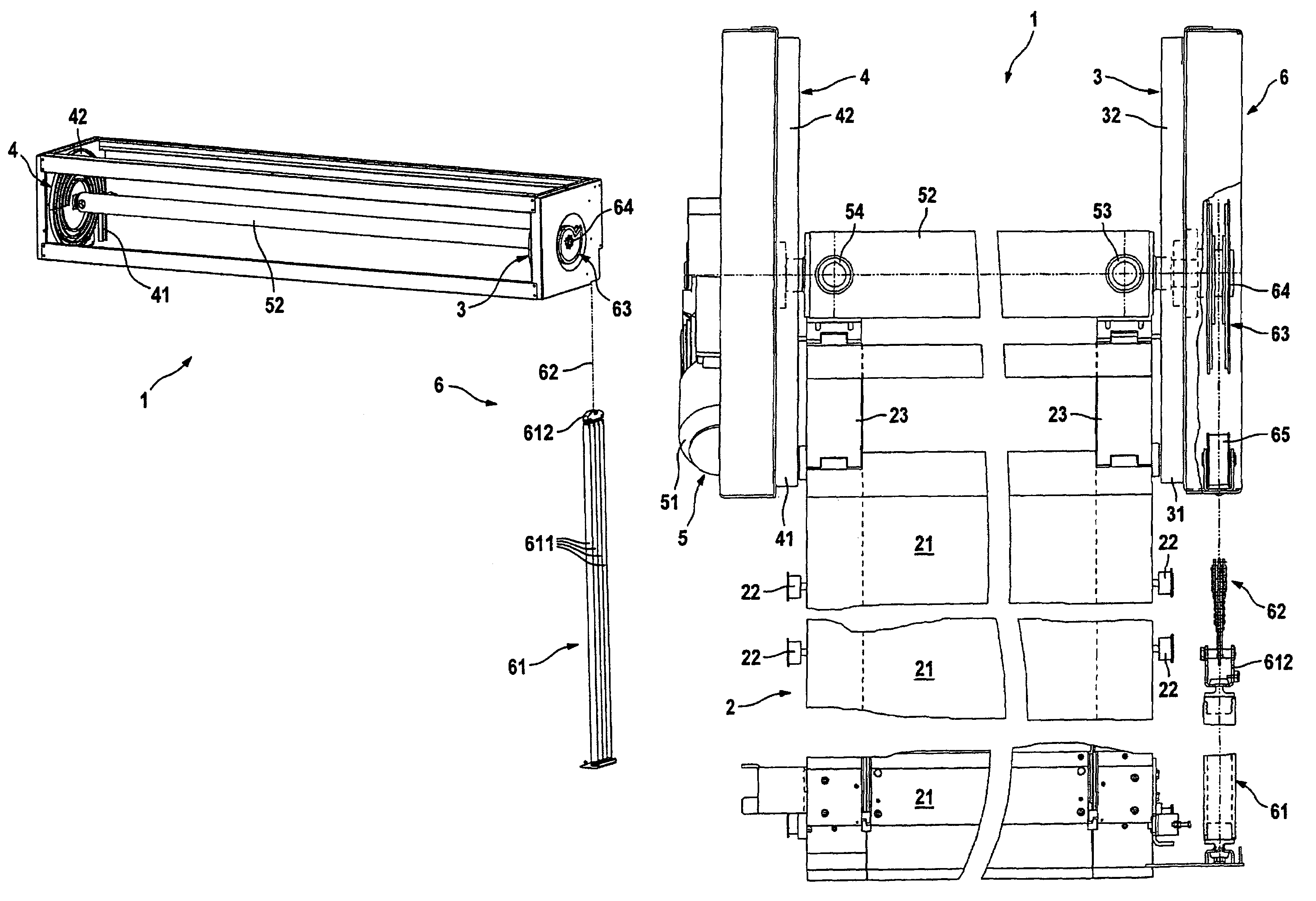
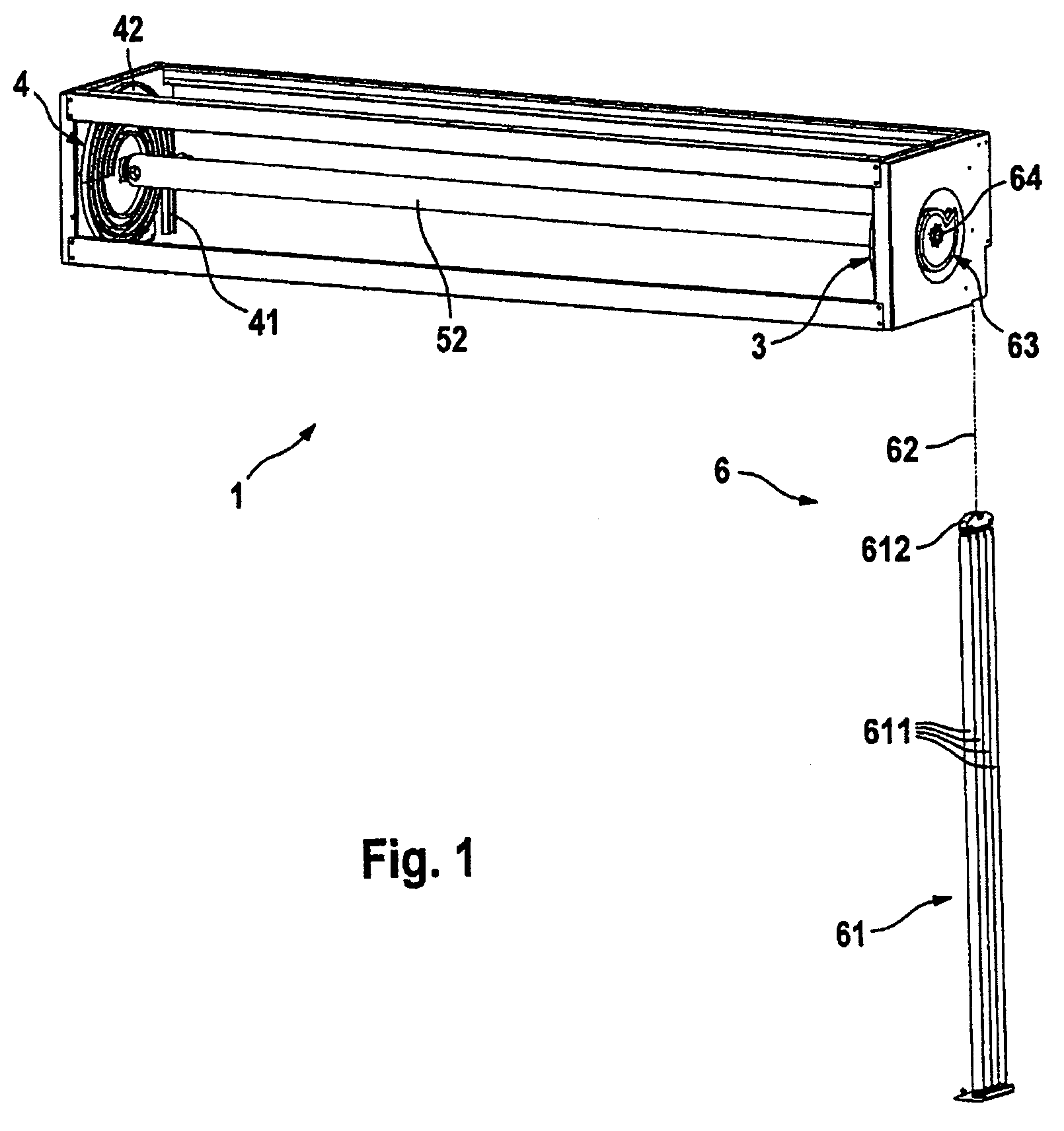
[0036]According to the illustrations in FIGS. 1 to 3, a lifting door 1 which is embodied as a roller door has a door leaf 2 which has lamellas 21 which are coupled to one another in an articulated manner and which are guided in lateral guides 3 and 4 by means of rollers 22. The rollers 22 are mounted here on lateral hinge belts 23 which pick up the tensile loads and thrust loads on the door leaf 2 and hold the lamellas 21.

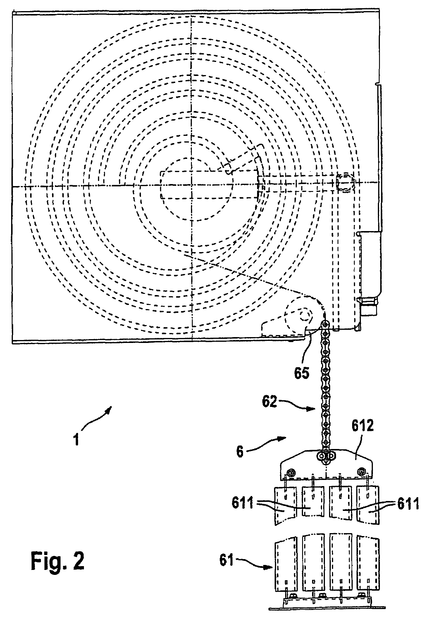
[0037]The guides 3 and 4 each have a vertical section 31 and 41, respectively, whose upper end can be seen in particular in FIG. 2 and which extends in a conventional way from the lintel-side end which is shown as far as the floor-side end of the lifting door 1, but this, along with the frames, is not shown in more detail in the figures. At the lintel side, the vertical sections 31 and 41 each open into a spiral section 32 and 42, respectively, which is in the form of a round spiral and in which the door leaf 2 is accommodated in the open position of the lifting do...


PUM


Abstract

A weight compensation device for a lifting door, includes a spring element and a tensile element, which can be wound onto or unwound from a winding device in such a way that the spring element achieves its greatest pre-tension when the door leaf is in the closed position and is essentially tension-free when the door leaf is in the open position. The tensile element is narrower at the end facing the winding device than at the end facing the spring element and the winding device includes a guide device, which is used to wind the tensile element in such a way that the wound layers lie adjacent to one another without making contact. To achieve this, the guide faces around the perimeter of the guide device have a continuously increasing radius in the winding direction. This enables the provision of a weight compensation device that achieves the torques required for effective weight compensation by means of a simple construction. This also relates to a lifting door that is equipped with a weight compensation device of this type.

Description

[0001]This application is the U.S. national phase of International Application No. PCT / EP2006 / 009973, filed 16 Oct. 2006, which designated the U.S., and claims priority to German Patent Application No. 10 2005 049 585.0, filed 17 Oct. 2005, the entire contents of each of which are hereby incorporated by reference.RELATED APPLICATION[0002]This application is related to copending, commonly assigned application Ser. No. 12 / 089,815 filed Apr. 10, 2008, entitled HIGH SPEED INDUSTRIAL ROLLER DOOR, which names Messrs. Rejc, Sentijurc and Breznikar as co-inventors (published as US-2008-0251220 A1).BACKGROUND[0003]1. Technical Field[0004]The invention relates to a weight compensation device for a lifting door, in particular for a high-speed industrial door, having a spring element, a tensile element and a winding device, wherein one end of the spring element can be secured to the floor, wherein the tensile element is attached by one end to the spring element and by the other end to the windi...

Claims


Application Information

Patent Timeline
Patent Type & Authority Patents(United States)
IPC IPC(8): E06B9/08E05D13/00E05F1/00E05F15/00
CPCE06B9/08E06B9/62E06B9/70Y10T16/64Y10T16/63
Inventor REJC, GABRIJELSENTJURC, MATJAZBREZNIKAR, JOZE
Owner EFAFLEX INZENIRING D O O LJUBLJANA
Why Eureka
Try Eureka