Segmented core plate and friction disc

a core plate and friction disc technology, applied in the direction of friction clutches, brake discs, clutches, etc., can solve the problems of multi-step manufacturing processes, waste of material in blanking out core plates, and large waste of friction rings and annular core plates, so as to reduce the amount of scrap material and increase the efficiency of steel core plates

Active Publication Date: 2010-09-21
BORGWARNER INC
View PDF56 Cites 48 Cited by
  • Summary
  • Abstract
  • Description
  • Claims
  • Application Information

AI Technical Summary

Benefits of technology

[0010]The present invention increases the efficiency of manufacturing steel core plates and separator plates by reducing the amount of scrap material from the manufacturing process.

Problems solved by technology

In the manufacturing process, blanking out of friction rings and annular core plates produces considerable waste.
Although these and other similar methods reduce the waste friction material, the multi-step manufacturing processes and waste of material in blanking out the core plate remains.

Method used


Image

  • Segmented core plate and friction disc
  • Segmented core plate and friction disc
  • Segmented core plate and friction disc

Examples


Embodiment Construction

[0032]The present invention is useful for both producing core plates having either prime or non-prime number of spine teeth on the core plates. According to the present invention, the segments are considered “prime” if the number of spine teeth on the disc is divisible by three or five segments.

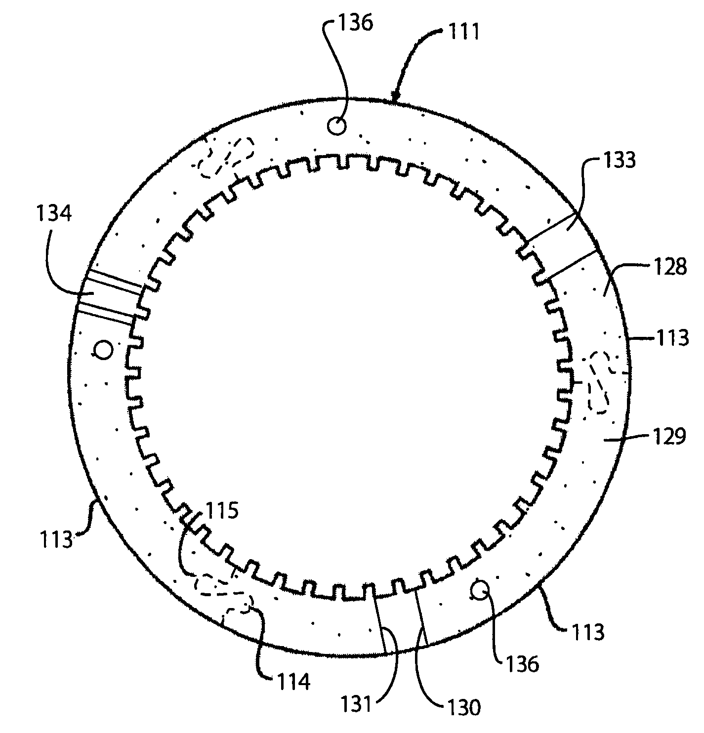
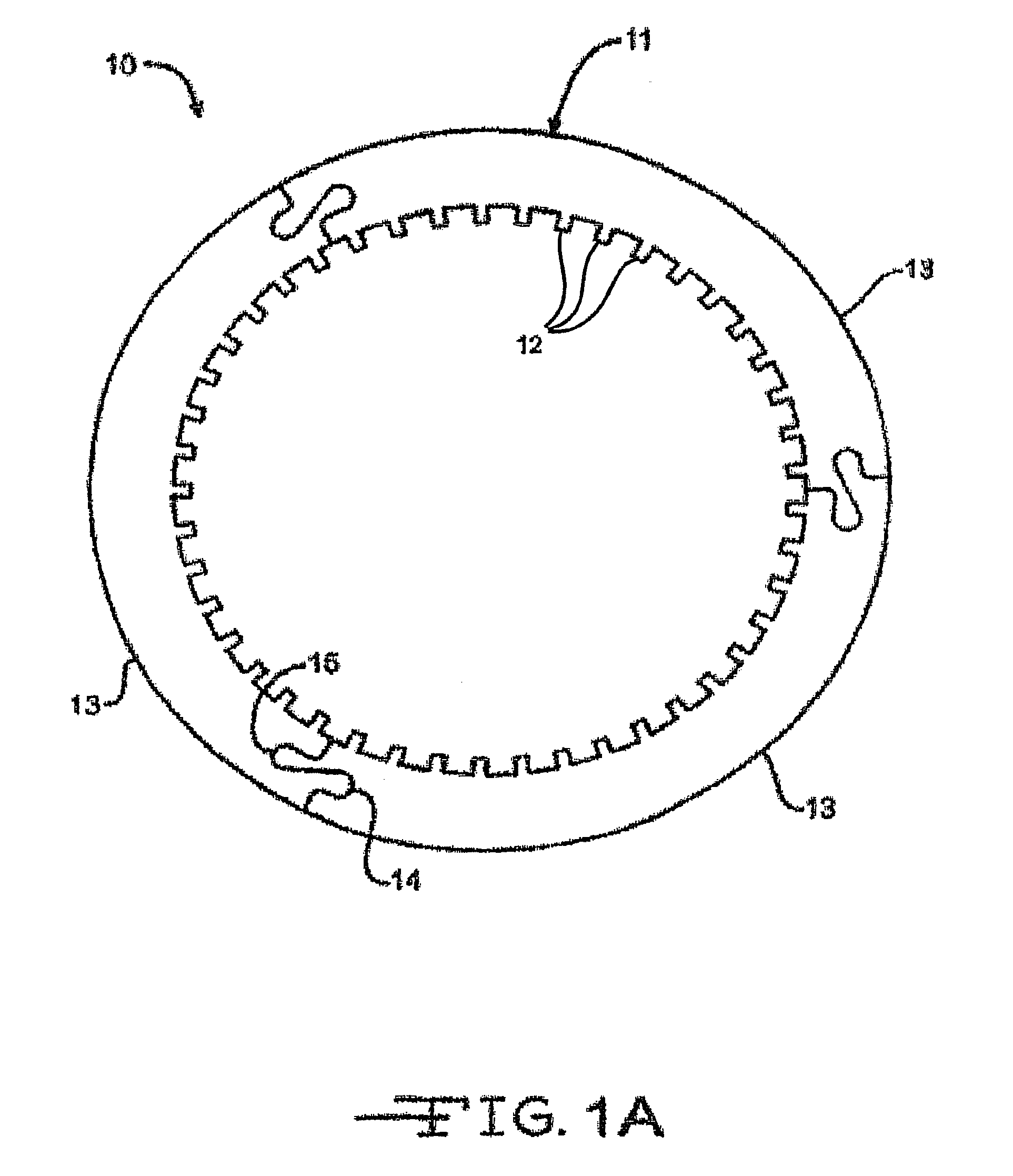
[0033]FIG. 1A shows a multi-plate clutch pack 10 for an automatic transmission or for other suitable clutch plate applications. The multi-plate clutch pack 10 includes a plurality of plates. For ease of explanation, one plate will be discussed in detail. The core plate 11 has a plurality of teeth 12. The teeth 12 may be on either the inner or outer periphery of the plate 11. The core plate 11 is comprised of three identical arcuate segments 13. Each segment 13 has a tab 14 and a slot 15 at opposing ends of the segment. The tab 14 and the slot 15 at either end are complimentary to and conformably receiving a tab 14 in a slot 15 in the next adjacent segment. It is to be understood that other sh...


PUM


Abstract

Segmented steel core plates for either double sided or single sided wet clutch friction plates or separator plates and a process for making the same are disclosed.

Description

CROSS REFERENCE TO RELATED APPLICATIONS[0001]This application claims the benefit of U.S. provisional patent application Ser. No. 60 / 775,492 filed on Feb. 21, 2006.[0002]The present invention relates to segmented steel core plates for either double sided or single sided wet clutch friction plates or separator plates and a process for making the same.BACKGROUND OF THE INVENTION[0003]The present invention relates to steel core plates or discs which are used in multi-plate wet clutch packs for automatic transmissions or transfer cases for vehicles or other friction clutch applications where an annular core plate is segmented with interlocking end portions to form an annular ring. Annular friction rings or discs are conventionally used in wet clutch packs of interleaved clutch plates that are alternately connected to an inner hub and an outer drum of a clutch assembly. The clutch plates are engaged to rotate the parts of the clutch assembly together by a hydraulically or spring-actuated ...

Claims


Application Information

Patent Timeline
Patent Type & Authority Patents(United States)
IPC IPC(8): F16D13/64
CPCF16D13/648F16D2069/004F16D69/00F16D13/64F16D65/12
Inventor KEATING, MARTIN P.ROCHE, MICHAELWAGNER, MICHAELNEUBAUER, DIRK
Owner BORGWARNER INC
Why Eureka
Try Eureka