Fuel injection valve device

a fuel injection valve and valve body technology, applied in the direction of fuel injection pumps, machines/engines, other domestic objects, etc., can solve the problems of large deflection of the nozzle hole plate, large-scale fuel injection valve, and easy stress concentration

Inactive Publication Date: 2010-09-21
MITSUBISHI ELECTRIC CORP
View PDF15 Cites 10 Cited by
  • Summary
  • Abstract
  • Description
  • Claims
  • Application Information

AI Technical Summary

Benefits of technology

[0008]To improve fuel spray characteristics such as atomization in the fuel injection valves, it has been conventional to adopt such means as increasing fuel pressure, thinning a nozzle hole plate or the like. In such means, however, the fuel injection valve for cylinder injection of fuel is normally high in fuel pressure (for example, 20 MPa), and therefore when thinning the nozzle hole plate, deflection of the nozzle hole plate becomes large due to application of fuel pressure. Thus, a problem exists in that stress concentration is easy to occur at a notch part between the nozzle hole plate and the weld part of the nozzle. To cope with this, it has been necessary to increase strength of the nozzle hole plate, which eventually results in a large-scaled fuel injection valve.
[0010]The present invention was made to solve the above-discussed problems, and has an object of providing a fuel injection valve device capable of thinning a nozzle hole plate and expanding a adjustable range of fuel spray characteristics by a construction for reducing stress concentration that occurs at the weld part of the nozzle hole plate.
[0012]In the fuel injection valve device of above construction according to the invention, since coefficient of stress concentration applied to a notch part at the tip of the weld part can be made small, deflection of the nozzle hole plate is suppressed and moment produced at the time of welding is made small. As a result, there is an advantage such that thickness of the nozzle hole plate can be established as small as possible even in case of high fuel pressure.

Problems solved by technology

In such means, however, the fuel injection valve for cylinder injection of fuel is normally high in fuel pressure (for example, 20 MPa), and therefore when thinning the nozzle hole plate, deflection of the nozzle hole plate becomes large due to application of fuel pressure.
Thus, a problem exists in that stress concentration is easy to occur at a notch part between the nozzle hole plate and the weld part of the nozzle.
To cope with this, it has been necessary to increase strength of the nozzle hole plate, which eventually results in a large-scaled fuel injection valve.
Therefore, a stress concentration takes place at this notch part, which may result in a fatigue failure even in case of a minute deflection due to moment of the nozzle hole plate caused by high fuel pressure.
Thus, there has been a limit in application of high fuel pressure or thinning the nozzle hole plate.

Method used


Image

  • Fuel injection valve device
  • Fuel injection valve device
  • Fuel injection valve device

Examples


embodiment 1

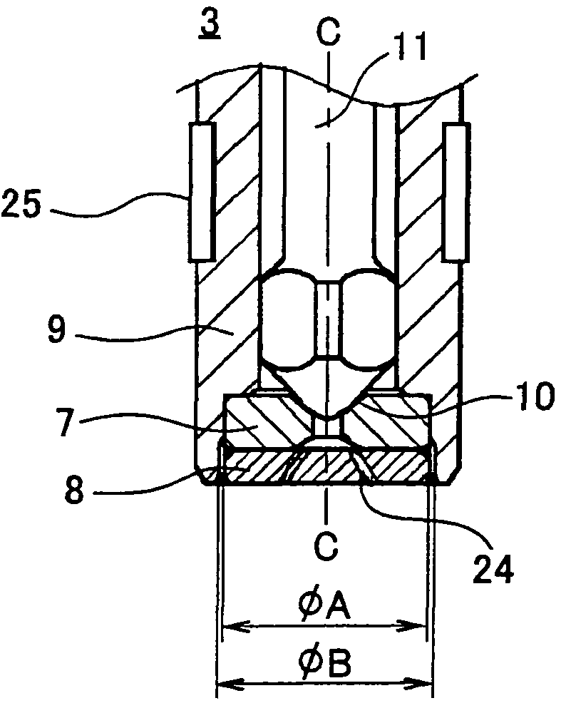
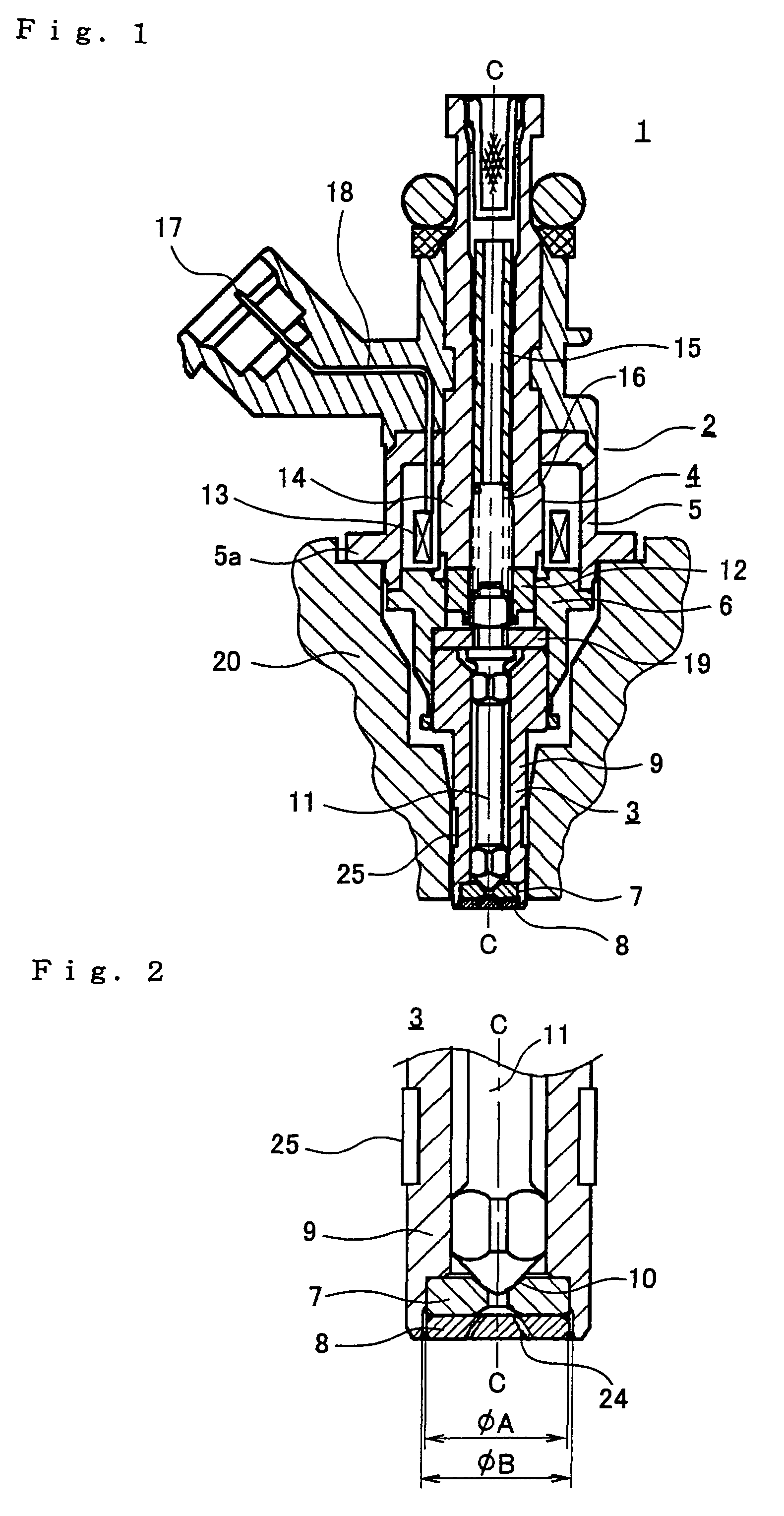
[0020]Embodiment 1 of the invention is hereinafter described with reference to the accompanying drawings. FIG. 1 shows a longitudinal sectional view of an entire construction of a fuel injection valve device according to Embodiment 1 of the present invention, and FIG. 2 shows an enlarged view of an essential part of a tip part of the valve device of FIG. 1. Referring to FIGS. 1 and 2, a fuel injection valve 1 mainly consists of a housing 2, a nozzle member 3 disposed inside at the end part of this housing 2, and a solenoid part 4 disposed inside at the intermediate part of the housing 2.

[0021]The mentioned housing 2 consists of a yoke part 5 having a flange 5a for mounting the fuel injection valve 1 on a cylinder head 20, and a holder 6 connected to one and of the yoke part 5. The mentioned nozzle member 3 is shaped into a cylinder provided with steps, and consists of a nozzle 9 to which a valve seat 7 and a nozzle hole plate 8 are fixed at the tip by a later-described method; a nee...

embodiment 2

[0032]Now referring to FIG. 5, Embodiment 2 of the invention is described. In this Embodiment 2, the same construction as in the foregoing Embodiment 1 is employed except that configuration of a nozzle hole plate is different. More specifically, in the nozzle hole plate 81 of this Embodiment 2, a thickness T of the outer circumference thereof is formed to be larger than a thickness t of the central part in order to suppress the moment due to fuel pressure of the nozzle hole plate. A plurality of inclined jet holes 24 is formed on this nozzle hole plate 81. Supposing that length of a jet hole 24 is L, diameter of the jet hole 24 is D, it has been acknowledged that atomization of fuel liquid injected through the mentioned jet holes 24 is desirably controlled by appropriately setting a ratio between L and D, i.e., L / D. In addition, it is preferable that the thickness T is set to be in the range of 1.0 to 1.5 mm and the thickness t is in the range of 0.4 to 0.7 mm.

[0033]Generally it is ...

embodiment 3

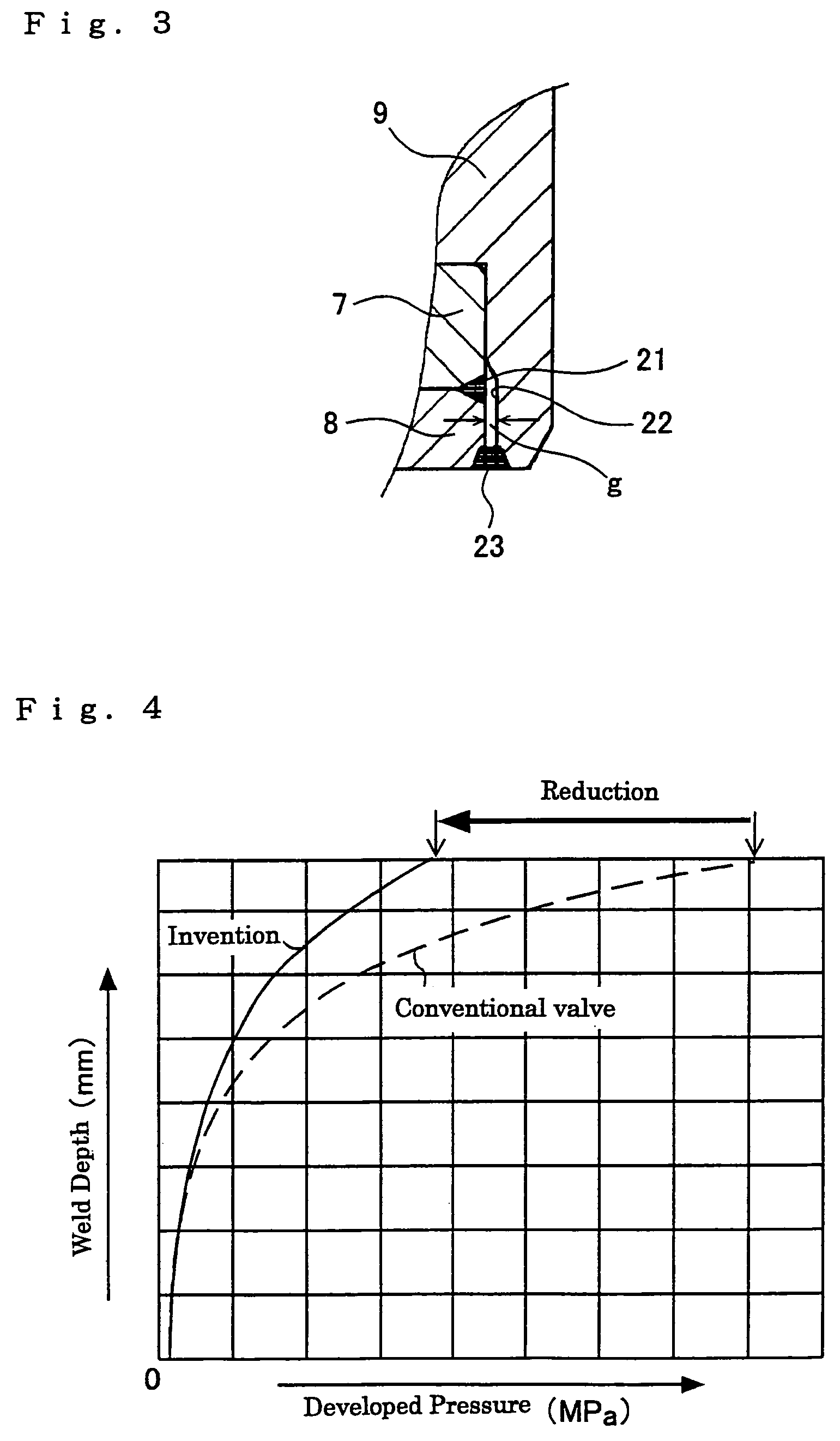
[0034]Now, referring to FIG. 6, Embodiment 3 of the invention is described. FIG. 6 is an enlarged view of an essential part of a tip of a valve member 3 of a fuel injection valve 1 and corresponds to FIG. 3 of the foregoing Embodiment 1. In this Embodiment 3, the same construction as in the foregoing Embodiment 1 is employed except that configuration of a gap 22a is different. That is, in the foregoing Embodiment 1, a step portion 22 is formed on the end of the nozzle in order to provide an even gap g on the entire circumference between the nozzle hole plate 8 and the nozzle. On the other hand, in this Embodiment 3, a step portion 22 is formed on the valve seat 7 and nozzle hole plate 8 side in order to provide an even gap g. As a result of such construction, since it is not necessary to apply any machining for forming the gap to the nozzle 9, a nozzle can be configured with high accuracy.


PUM

PropertyMeasurementUnit
diameteraaaaaaaaaa
thicknessaaaaaaaaaa
thicknessaaaaaaaaaa

Abstract

A fuel injection valve device is capable of thinning a nozzle hole plate and improving fuel spray characteristics by a construction for reducing stress concentration that occurs at the weld part of the nozzle hole plate. The fuel injection valve device includes: a nozzle having a fuel passage inside and in which a valve seat is formed at an end; a needle valve for opening and closing the fuel passage by coming in contact with and separating from the valve seat; and an nozzle hole plate that is disposed at the tip of the nozzle and injects a fuel in the fuel passage at the time of opening the needle valve. The nozzle hole plate and the nozzle are fixed by welding in a state of forming an even gap between them.

Description

BACKGROUND OF THE INVENTION[0001]1. Field of the Invention[0002]The present invention relates to a fuel injection valve device for use in, for example, automobile engines and, more particularly, to a fuel injection valve device provided with a nozzle hole plate for atomization of fuel.[0003]2. Description of Related Arts[0004]Under the recent trend of tightening the regulations of exhaust gas, in the field of fuel injection valve device for use in automobile engines, it has been increasingly demanded to improve fuel spray characteristics. To cope with this demand, several attempts of fuel injection valve device have been proposed. In those known fuel injection valve devices, a nozzle hole plate having a plurality of nozzle holes on the downstream side of a valve member consisting of a valve disc and a valve seat is disposed so that atomized fuel is injected from every nozzle hole into each cylinder head of an engine.[0005]For example, the Japanese Patent Publication (unexamined) No....

Claims


Application Information

Patent Timeline
Patent Type & Authority Patents(United States)
IPC IPC(8): F02M59/00B05B1/00B05B1/30F02M51/00B21K21/08
CPCF02M61/1853F02M61/1886F02M51/0675F02M61/12Y10T29/49433F02M2200/8084F02M2200/9053Y10S239/19F02M2200/8053
Inventor ONISHI, YOSHIHIKOTOCHIYAMA, SHIGENOBUKITAGAWA, KAZUNORI
Owner MITSUBISHI ELECTRIC CORP
Why Eureka
Try Eureka