Finite element model of a keratoconic cornea

a keratoconus and end-element model technology, applied in the field of ophthalmic diagnostic equipment and procedures, can solve the problems of difficult, difficult, if not impossible, to locate and directly measure the biomechanical stresses and strains, and the keratoconus is not easily detected, so as to improve the accuracy and enhance the resultant topography measurement

Active Publication Date: 2010-09-21
HEIDELBERG ENGINEERING GMBH
View PDF16 Cites 4 Cited by
  • Summary
  • Abstract
  • Description
  • Claims
  • Application Information

AI Technical Summary

Benefits of technology

[0007]In accordance with the present invention, a system and method for diagnosing the onset of keratoconus in a cornea requires mapping the anterior surface of the cornea of an eye. Once the eye has been mapped, the resultant topography is fitted onto a finite element model (FEM), and the consequent tissue parameters are evaluated. Preferably, the mapping is accomplished while the eye is subjected to an externally imposed pressure that will be less than about 14 kPa. Mapping, however, can also be made with no added pressure, or at a series of different pressures. In any event, if employed, pressure is used to change the shape of the cornea and thereby enhance the resultant topography measurements. The mapped topographies are then fitted on a mathematical model of the cornea and biomechanical parameters in the cornea are taken from the model for the respective corneal configurations. Next, a computer is used to evaluate the biomechanical parameters. Based on this evaluation, a diagnosis is made as to whether the cornea is keratoconic. In this context, a topography mapped while the eye is under pressure may be more likely to give accurate information and, though mapping only one topography may suffice, additional information from different pressure topographies will improve precision.

Problems solved by technology

In the early stages of the disease, keratoconus is not easily detected.
Nevertheless, there are structural weaknesses in the corneal tissue, caused by lamella crossover in the early stages of the disease, that portend the disease.
It is extremely difficult, however, if not impossible to locate and directly measure the biomechanical stresses and strains that are characteristic of these weaknesses.

Method used


Image

  • Finite element model of a keratoconic cornea
  • Finite element model of a keratoconic cornea
  • Finite element model of a keratoconic cornea

Examples


Embodiment Construction

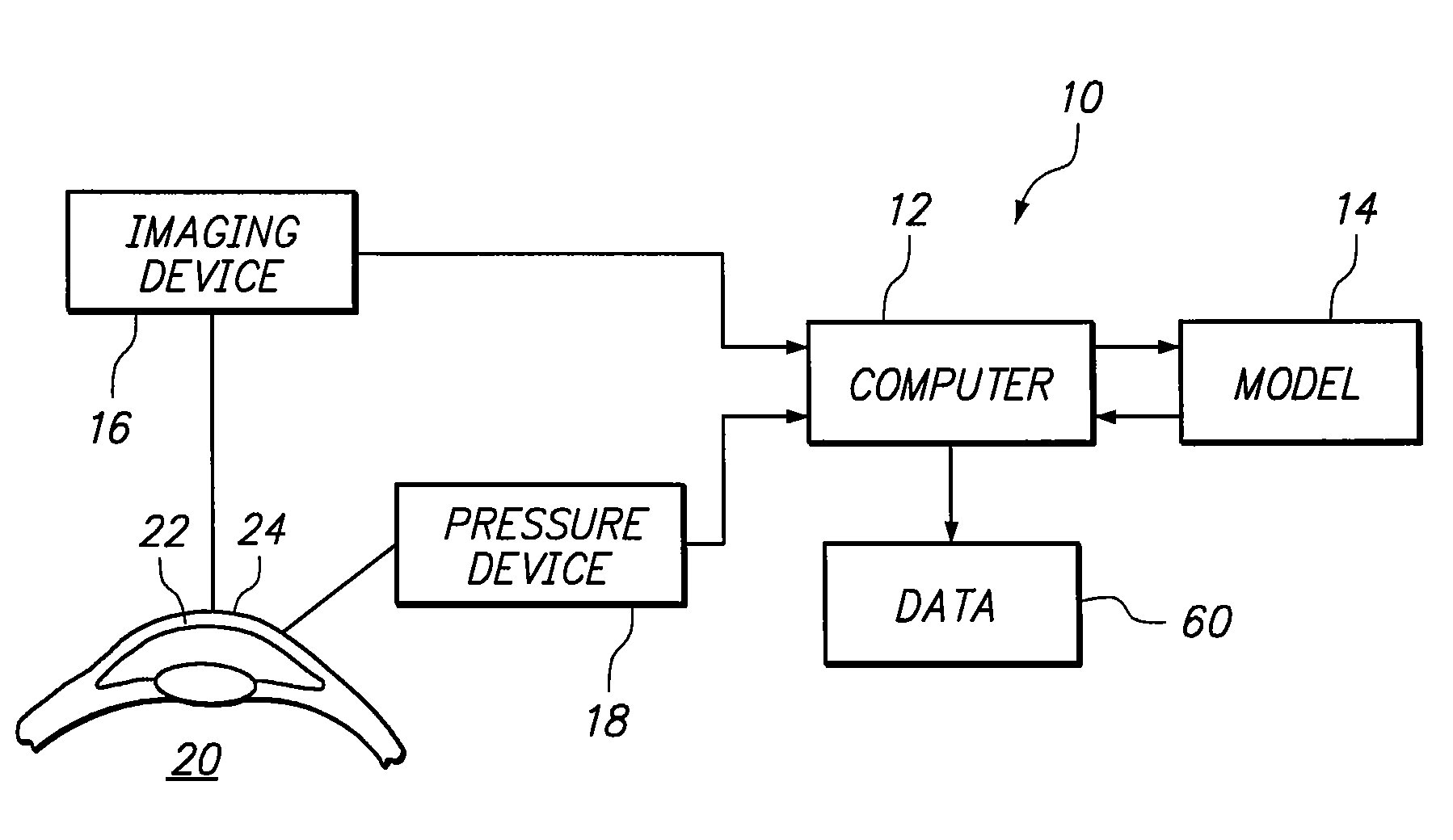
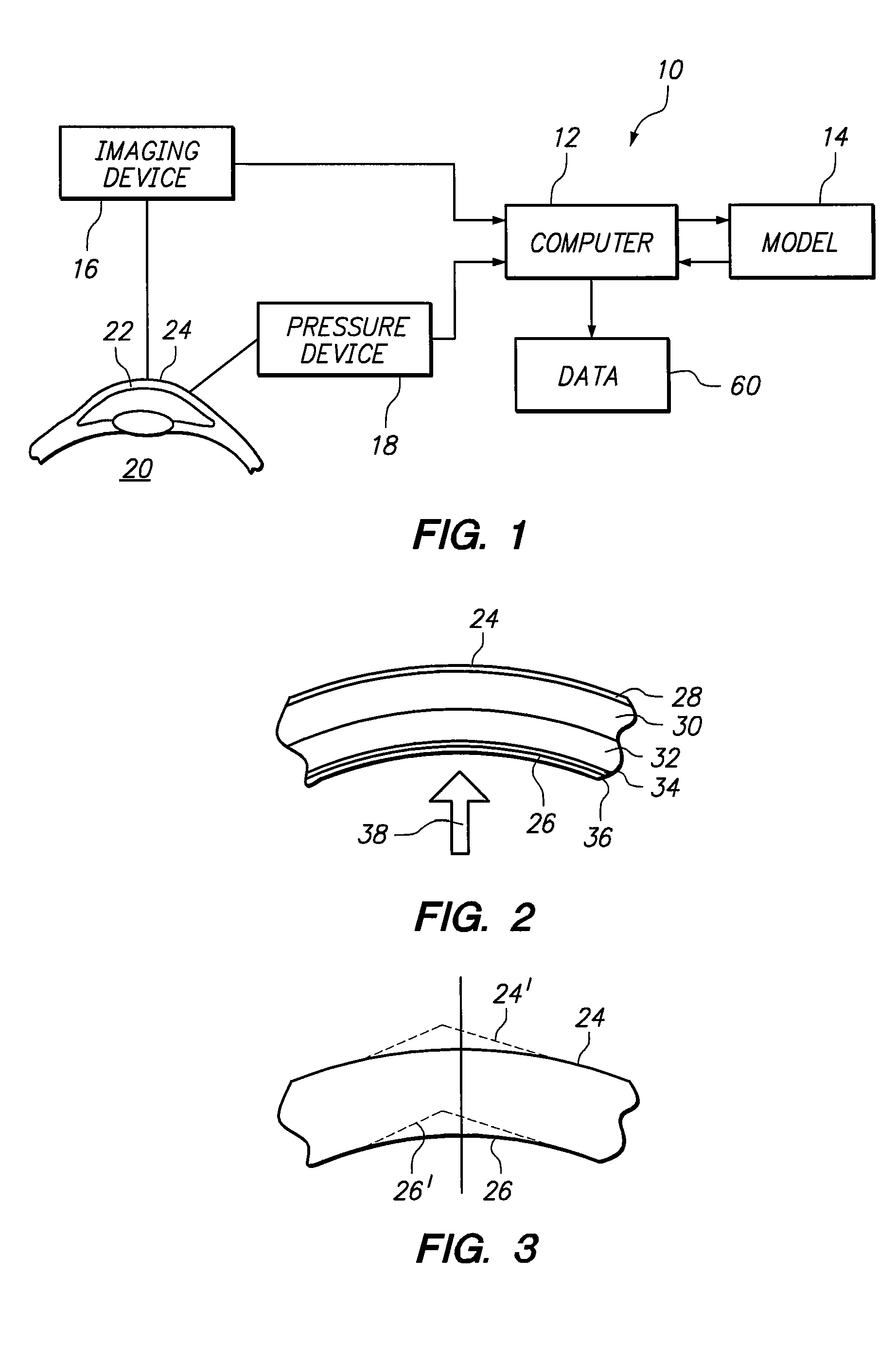
[0017]Referring initially to FIG. 1, a system for diagnosing keratoconus in accordance with the present invention is shown and is generally designated 10. As shown, the system 10 includes a computer 12 that is electronically interconnected with a mathematical model 14. Also interconnected with the computer 12 are an imaging device 16 and a pressure device 18. As indicated in FIG. 1, the imaging device 16 and the pressure device 18 are positioned to interact with an eye 20 of a patient (not shown). More particularly, the devices 16 and 18 are positioned to interact with the cornea 22 of the eye 20.

[0018]In FIG. 2, a cross section of the cornea 22 shows that, anatomically, the cornea 22 has five different identifiable layers of tissue. Between the anterior surface 24 and the posterior surface 26 of the cornea 22, and going in an anterior-posterior direction, the layers of the cornea 22 are: epithelium 28; Bowman's membrane 30; stroma 32; Descemet's membrane 34; and endothelium 36. Str...


PUM


Abstract

A system and method for diagnosing the onset of keratoconus in a cornea requires subjecting the cornea of an eye to a pressure that changes its shape. A topography of the cornea's anterior surface (possibly, the posterior surface also) is mapped. The mapped topography is then fitted on a mathematical model of the cornea. Measurements corresponding to biomechanical parameters in the cornea are then taken from the model. Next, a computer is used to evaluate the biomechanical parameters to diagnose whether the cornea is keratoconic.

Description

FIELD OF THE INVENTION[0001]The present invention pertains generally to ophthalmic diagnostic equipment and procedures. More particularly, the present invention pertains to diagnostic systems and methods that employ mathematical models of the cornea for diagnosing corneal diseases, such as keratoconus. The present invention is particularly, but not exclusively, useful as a system and method for making an early diagnosis of keratoconus, to determine whether a cornea is a proper candidate for subsequent refractive surgical procedures.BACKGROUND OF THE INVENTION[0002]By definition, keratoconus is a non-inflammatory, usually bilateral protrusion of the cornea, the apex being displaced downward and nasally. Essentially, keratoconus is caused by a thinning of the cornea that will typically result in asymmetric astigmatism. Another aspect of the disease, however, also deserves consideration. Specifically, this consideration is the fact that keratoconus causes a loss of corneal tissue that ...

Claims


Application Information

Patent Timeline
Patent Type & Authority Patents(United States)
IPC IPC(8): A61B3/14
CPCA61B3/107
Inventor BILLE, JOSEF F.
Owner HEIDELBERG ENGINEERING GMBH
Why Eureka
Try Eureka