Ultrasonic monitor for measuring blood flow and pulse rates

a technology of ultrasonic monitors and pulse rates, applied in tomography, instruments, applications, etc., can solve problems such as signal load

Inactive Publication Date: 2010-09-21
SALUTRON
View PDF30 Cites 83 Cited by
  • Summary
  • Abstract
  • Description
  • Claims
  • Application Information

AI Technical Summary

Benefits of technology

[0024]In one embodiment, the monitor is implemented on a circuit board, such as a printed circuit board (PCB). By implementation on a PCB, the monitor system can be integrated to a very small footprint. This allows for a very efficient system with a much lower power requirement than prior systems. A pair of transducers is mounted directly to the PCB. This results in higher efficiency than previous implementations where the transducers were attached to some supporting structure, such as a glass base plate, thereby causing a signal load.
[0026]In some embodiments, a multi-layer gel pad is used to transmit ultrasonic signals between the ultrasonic monitor and the skin of the subject. The gel pad includes a gel layer adhered to a membrane layer. The membrane layer can be applied to one or more surfaces of the gel layer and prevents diluents within the gel layer from escaping. This is advantageous when the gel includes elements that are not intended to make contact with the living subject or other surfaces.
[0027]In another embodiment, the PCB can be entirely encapsulated in plastic, a water resistant gel, or a combination of the two. This provides for keeping the system of the ultrasonic monitor protected from debris such as dirt, dust and water.

Problems solved by technology

This results in higher efficiency than previous implementations where the transducers were attached to some supporting structure, such as a glass base plate, thereby causing a signal load.

Method used


Image

  • Ultrasonic monitor for measuring blood flow and pulse rates
  • Ultrasonic monitor for measuring blood flow and pulse rates
  • Ultrasonic monitor for measuring blood flow and pulse rates

Examples


Embodiment Construction

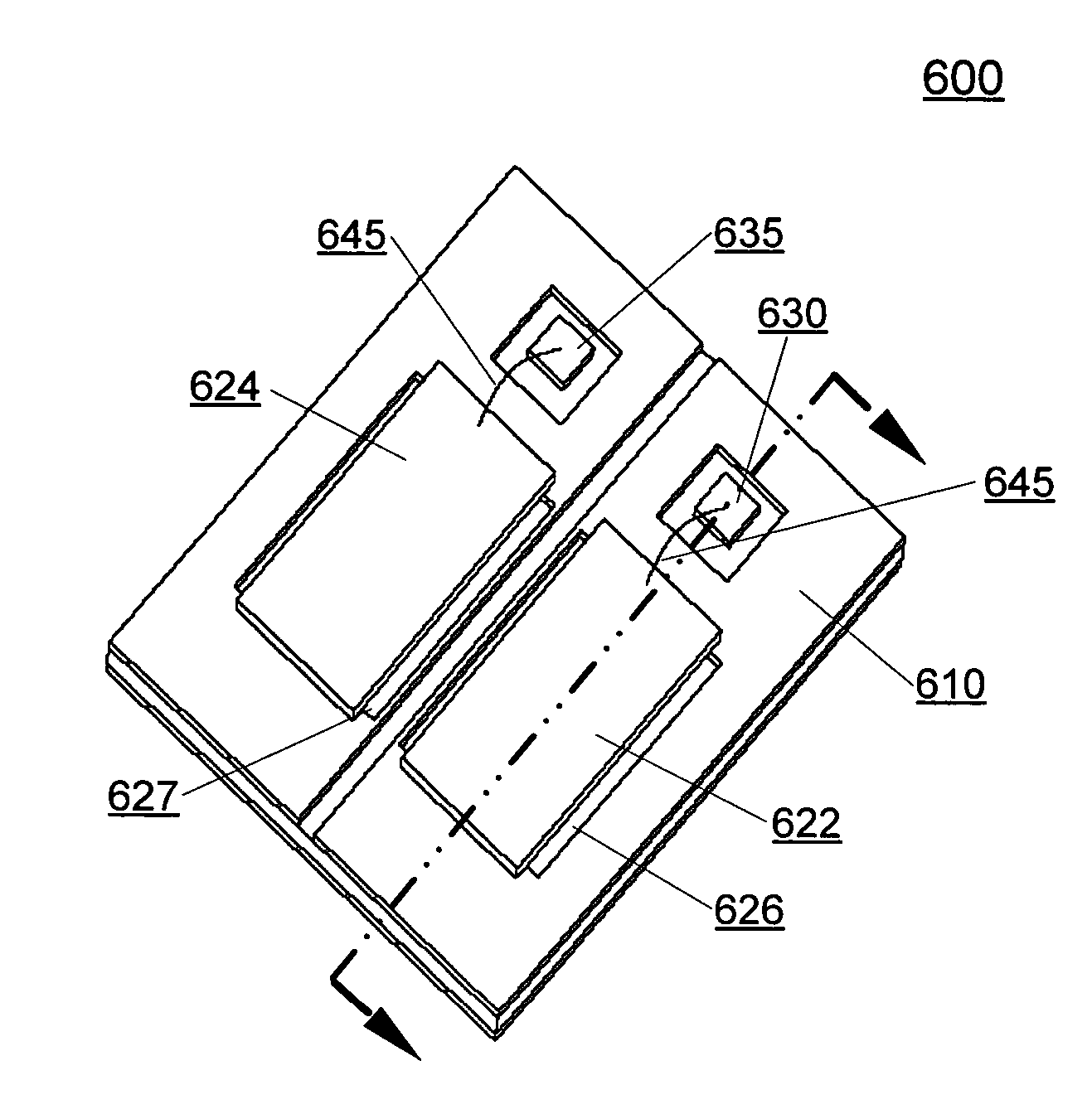
[0055]The present invention, roughly described, pertains to ultrasonic monitors. The ultrasonic monitor uses ultrasonic signals to measure movement inside the body of a living subject. The movement may be a heart contraction, flowing blood or movement of the blood vessel itself. From information collected from these movements, electronics within the monitor may determine blood flow rate, heart rate, or pulse rate of the living subject.

[0056]In one embodiment, the ultrasonic monitor measures blood flow through an artery of a person. The ultrasound signals reflected by blood vessel expansion (expansion due to blood moving through the vessel) have a frequency range similar to that of noise caused by muscle artifacts and tissue movement. The ultrasound signals reflected by the flowing blood itself have a frequency range higher than muscle and tissue related noise. As a result, the signals reflected by flowing blood are easier to process to find the rate values than those reflected by ex...


PUM


Abstract

An ultrasonic monitor implemented on a PCB includes a gel pad comprised of a gel layer and a membrane layer. Ultrasonic signals are transmitted between the ultrasonic monitor and a living subject through the gel pad. An air gap is formed in the PCB underneath transducer elements to provide for more efficient signal transmission. These features provide for a low power, low cost, more efficient ultrasonic monitor. The entire ultrasonic monitor may be encapsulated in plastic, a gel, or both to provide water resistant properties.

Description

CROSS REFERENCE TO RELATED INVENTION[0001]The instant non-provisional applications is related to the following patent applications, all of which are hereby incorporated by reference in their entirety:[0002]U.S. patent application Ser. No. 10 / 346,296, filed on Jan. 15, 2003;[0003]U.S. patent application Ser. No. 10 / 758,608, filed on Jul. 14, 2004, which in turn is a continuation-in-part of parent non-provisional patent application Ser. No. 10 / 346,296, filed Jan. 15, 2003; and[0004]U.S. patent application Ser. No. 10 / 991,115, filed the same day as the present application, entitled “GEL PAD FOR USE WITH AN ULTRASONIC MONITOR”, having inventors Thomas Ying-Ching Lo, Rong Jong Chang.BACKGROUND OF THE INVENTION[0005]1. Field of the Invention[0006]The present invention relates to ultrasonic monitors for measuring heart rates and pulse rates in living subjects.[0007]2. Description of the Related Art[0008]Measuring heart and pulse rates in living subjects has become a valuable tool in physic...

Claims


Application Information

Patent Timeline
Patent Type & Authority Patents(United States)
IPC IPC(8): A61B8/14
CPCA61B5/411A61B5/681A61B8/02A61B8/06A61B8/4227A61B8/4281A61B8/4483G10K11/004A61B8/4472
Inventor LO, THOMAS YING-CHINGCHANG, RONG JONG
Owner SALUTRON
Why Eureka
Try Eureka