Armored building modules and panels—installation and removal

a technology of building modules and panels, applied in the direction of building roofs, parkings, building repairs, etc., can solve the problems of not providing rapid deployment of steel structures suitable for protecting against mortar impacts, and cannot be removed by a simple translation of the panel

Active Publication Date: 2010-09-28
KONTEK INDS
View PDF41 Cites 4 Cited by
  • Summary
  • Abstract
  • Description
  • Claims
  • Application Information

AI Technical Summary

Problems solved by technology

These prior arts have relied upon heavy materials, and more recently on expensive materials.
None of the prior arts have taken advantage of structures made mostly of common-grade steel plates.
And the prior art has not provided rapidly deployable steel structures suitable for protecting against mortar impacts and consequent mortar blasts.
Also, with the configurations disclosed in both these two patents, when one panel is positioned edge-to-edge between two neighboring panels, it cannot be removed by a simple translation of the panel in a direction perpendicular to a face of the panel.
But none of these are ideally designed to protect against mortar shells that travel at lower speeds and may have higher explosive energies.
Furthermore, none of these patents teach or suggest the design or use of modules from which to construct a panel.

Method used


Image

  • Armored building modules and panels—installation and removal
  • Armored building modules and panels—installation and removal
  • Armored building modules and panels—installation and removal

Examples


first embodiment

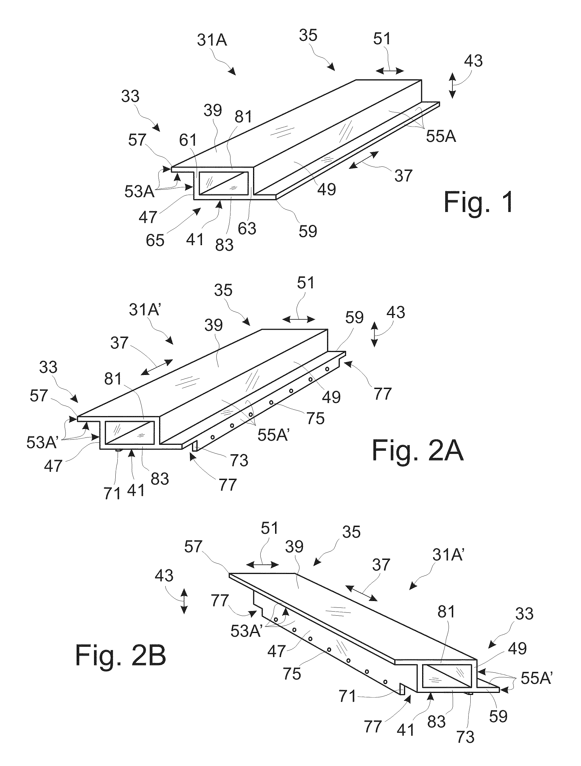
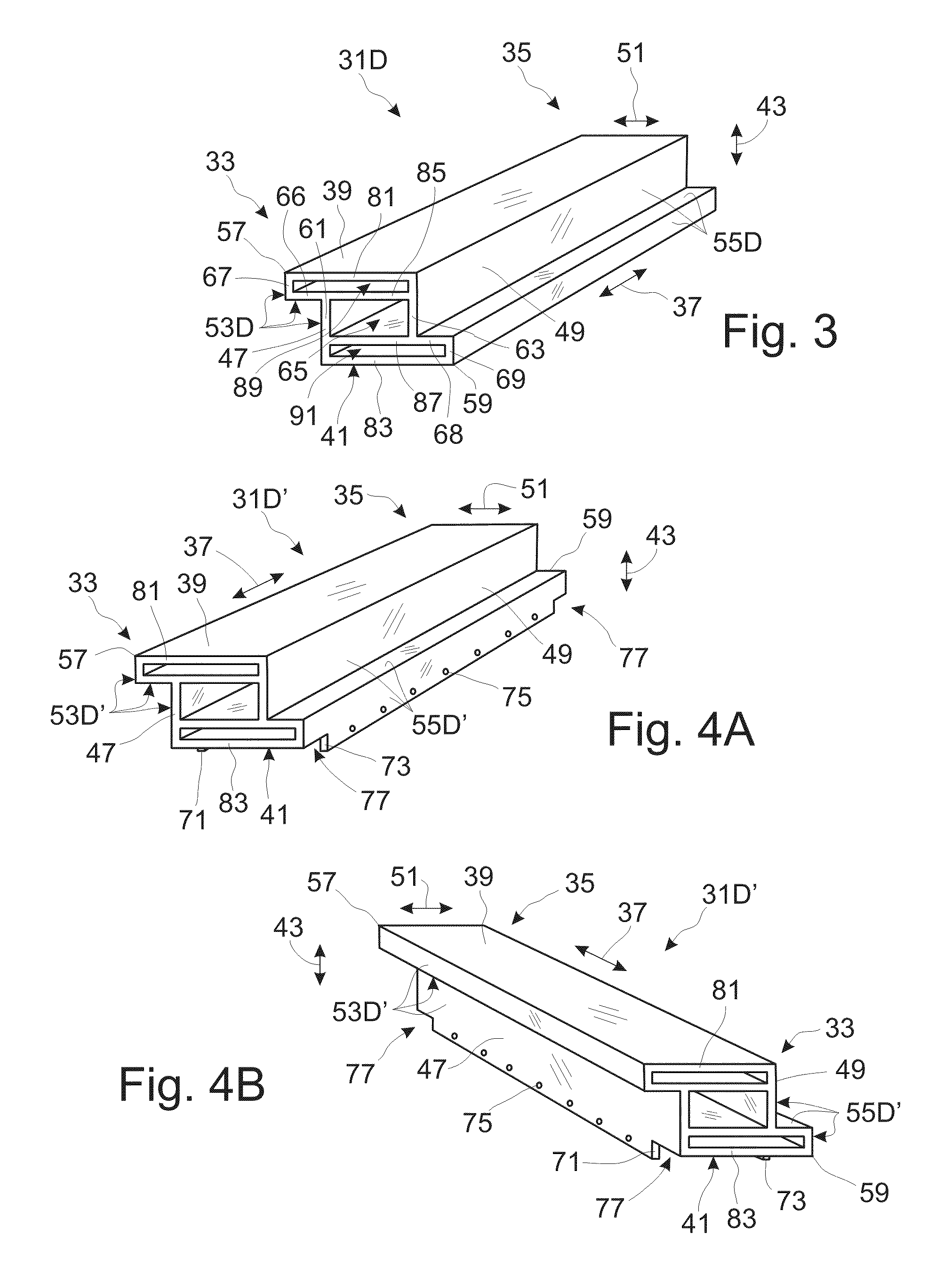
[0144]Thus the module 31A shown in FIG. 1 functions well as an armored building module. Constructed of strong material such as steel, its elongated structure comprising multiple (equally elongated) flanges 81,83 and webs 61,63 provide it with ample strength as a structural element and component in floors, walls, doors, partitions, and especially roofs. The composition of two separated plates 81,83 supported by two separated webs 61,63 can protect people and equipment from impacts, blasts, ballistics, and shrapnel when these threats strike one of the faces 39,41 facing outward from the protected space. All of the modules and panels made from the modules of this invention, including an armored building module 31A as shown in FIG. 1, are designed especially to withstand and structurally survive impacts, blasts, and shrapnel from mortars. One skilled in the art will appreciate that the use of high strength steels or lighter weight, high-strength aluminum or titanium material in any of t...

second embodiment

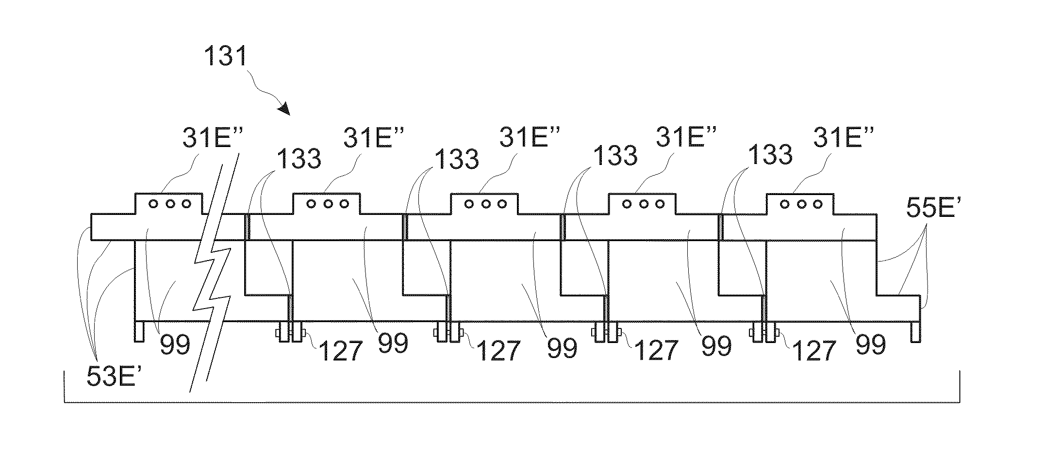
[0161]FIG. 9 shows a perspective view of an again-modified version 31E″ of the modified second embodiment of an armored building module 31E′ shown in FIG. 8C, further including first 111 and second 113 end means for securing modules to one another in end-to-end alignment in an end-to-end configuration (as shown in FIGS. 14, 15D, and 15E). These end means for securing modules to one another 111,113 are shown as tab-like features located at the ends of the module and include holes 75 for fasteners, wherein these tabs 111,113 are located on an opposite face of the module relative to the side-mounted tabs 71,73. Also shown is a side clearance in end tab 115 at each end of each end tab 111,113. This particular choice of placement of first and second end means for securing modules to one another 111,113 is preferred when the ends of the module 31E″ are to be supported by a stringer running parallel to the sideways directions and when positioned to support the module at the ends of the mod...


PUM


Abstract

Panels and their modules, such as for walls and roofs, are disclosed that provide armored shelter for protecting people and equipment from ballistic projectiles and mortar attacks. Each module is made from multiple co-parallel plates arranged in a stack, spaced apart, and held together along their sides by side elements. This is done in such a way that, when assembled side-by-side or end-to-end into panels, adjacent modules overlap one another to prevent straight-through seams yet allow any damaged module to be removed and replaced without moving adjacent modules. Space within a module, between plates and sides, can contain energy absorbing material in a variety of shapes. Plates serve as structural flanges, and side elements comprise structural webs, to permit each module to function as a structural beam. With such designs, the modules and panels are easily and quickly inserted and / or removed individually by a sequence of simple manipulations.

Description

CROSS-REFERENCE TO RELATED APPLICATIONS[0001]This application is a co-owned divisional application of parent application Ser. No. 11 / 123,624, titled “Armored Building Modules and Panels” and filed May 6, 2005. This application claims priority to that parent which is now U.S. Pat. No. 7,661,228, issued Feb. 16, 2010.STATEMENT REGARDING FEDERALLY SPONSORED RESEARCH OR DEVELOPMENT[0002]Not ApplicableTHE NAMES OF THE PARTIES TO A JOINT RESEARCH AGREEMENT[0003]Not ApplicableSEQUENCE LISTING OR PROGRAM, AND INCORPORATION-BY-REFERENCE OF MATERIAL SUBMITTED ON A COMPACT DISC[0004]Not ApplicableBACKGROUND OF THE INVENTION[0005]1. Field of the Invention[0006]This invention relates to armored building modules and panels, such as for walls and roofs, that provide armored shelter to protect people and equipment from ballistic projectiles and mortar attacks, and in particular to armored building modules each made from multiple, co-parallel, plates arranged in a stack but spaced apart and held tog...

Claims


Application Information

Patent Timeline
Patent Type & Authority Patents(United States)
IPC IPC(8): E04H1/00E04C3/00
CPCE04B7/20E04H9/10
Inventor NOLTE, ROGER ALLENSELKE, DONALD L.
Owner KONTEK INDS
Why Eureka
Try Eureka