
Rotary type compressor

a compressor and rotary technology, applied in the direction of machines/engines, liquid fuel engines, positive displacement liquid engines, etc., can solve the problems of weak strength of the receding part and difficult deformation, so as to reduce the size of the area, reduce the leakage of refrigerant, and strengthen the strength

Inactive Publication Date: 2010-09-28
DAIKIN IND LTD
View PDF14 Cites 41 Cited by
  • Summary
  • Abstract
  • Description
  • Claims
  • Application Information

AI Technical Summary

Benefits of technology

The present invention aims to reduce deformation of the end plate part in a rotary type compressor. The invention provides a compressor with a fixed member and a movable member that define a compression chamber. The fixed member has an end plate part with a receding part, a discharge valve, and a valve guard. The valve guard is mounted to the end plate part and restricts the deformation of the valve disc. The invention also provides a compressor with a cylinder, a piston, and a blade that divide the cylinder chamber into two chambers and compress fluid in the cylinder chamber. The valve disc has a receding part and a discharge valve that opens and closes the discharge passage. The valve guard is mounted to the end plate part and has a main body part and a fixation part that extends to outside of the receding part. The invention also provides a rotary type compressor where the discharge valve has a pin member and a clearance gap for allowing the base end side of the valve disc to move in the axial direction of the pin member. The invention aims to reduce deformation of the end plate part and improve the performance of the compressor.

Problems solved by technology

However, the strength of the receding part still remains weak and its deformation becomes problematic.

Method used


Image

  • Rotary type compressor
  • Rotary type compressor
  • Rotary type compressor

Examples


first embodiment

of the Invention

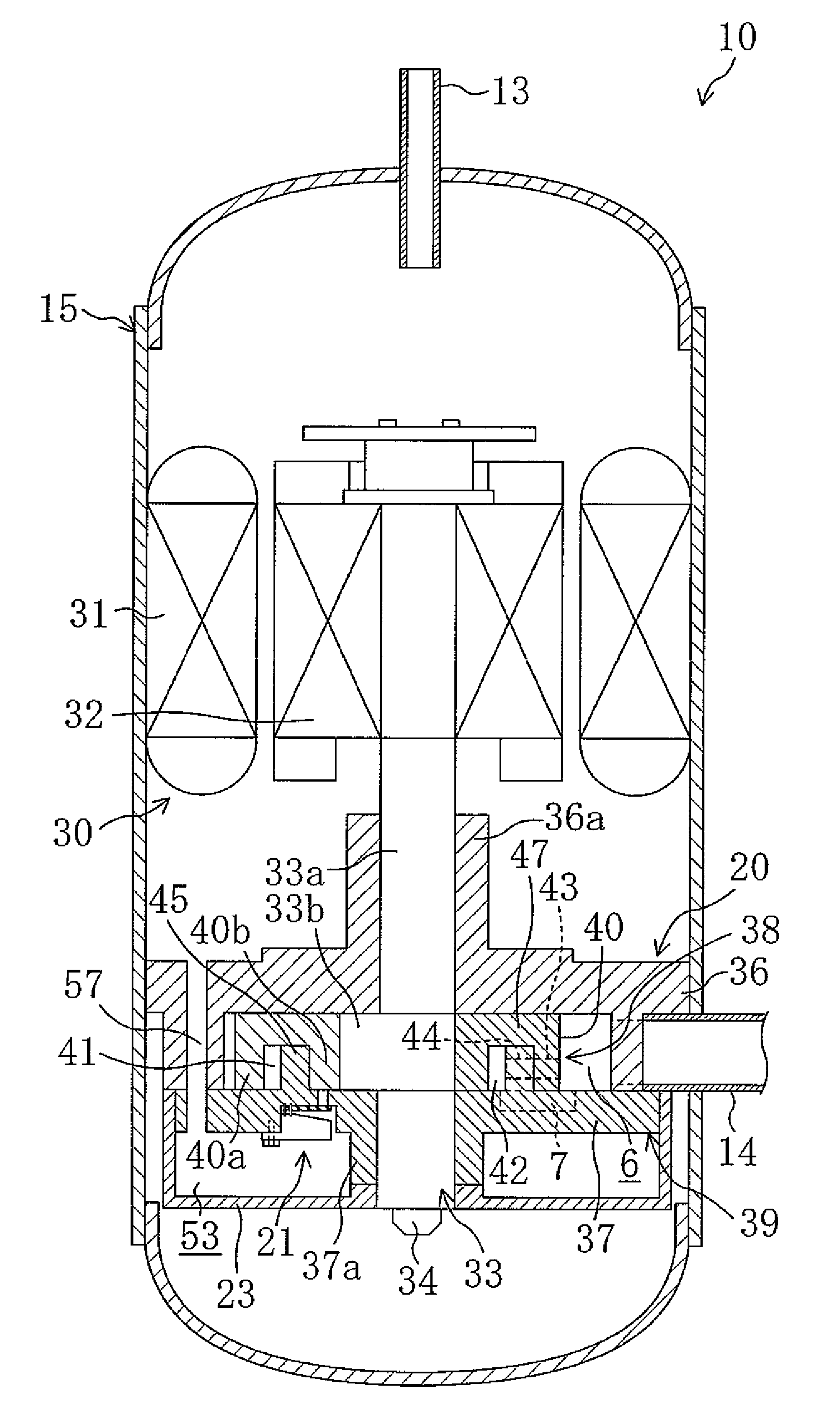
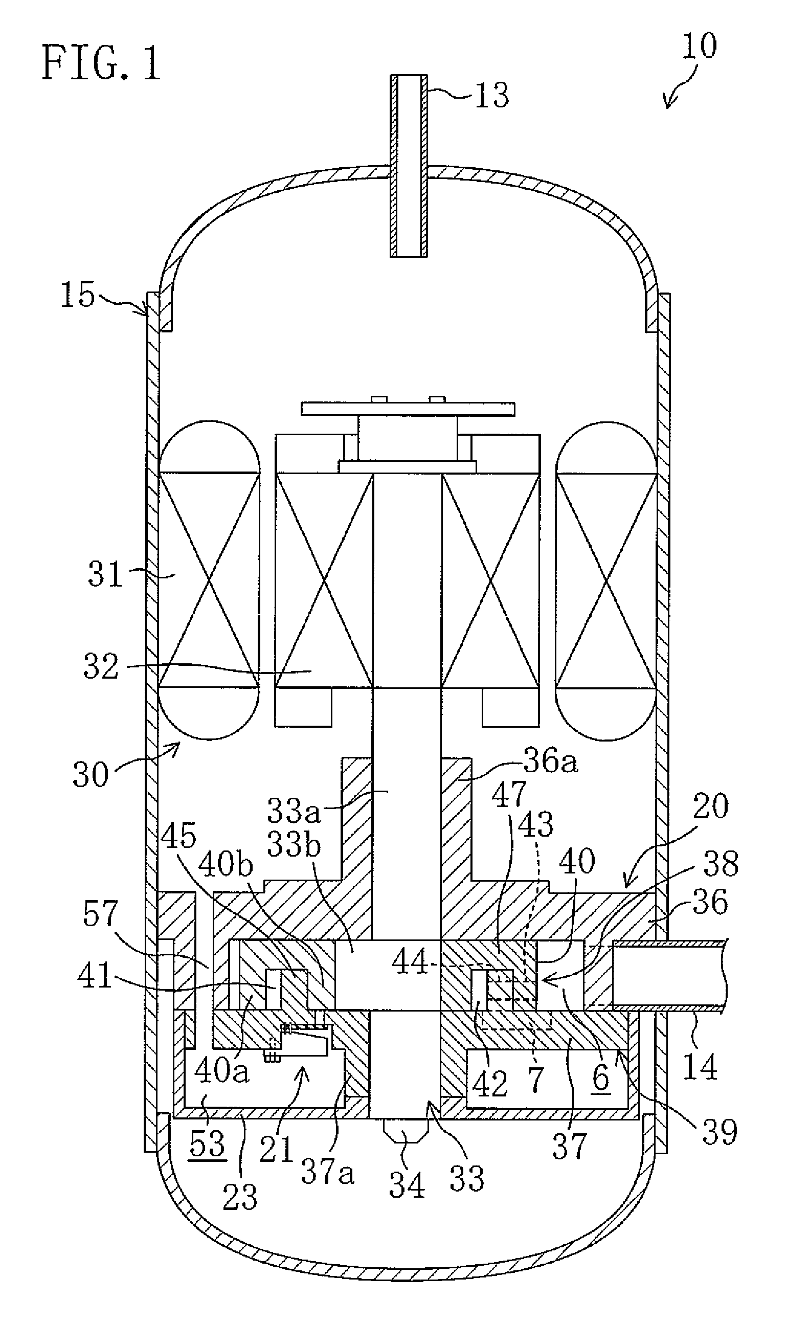
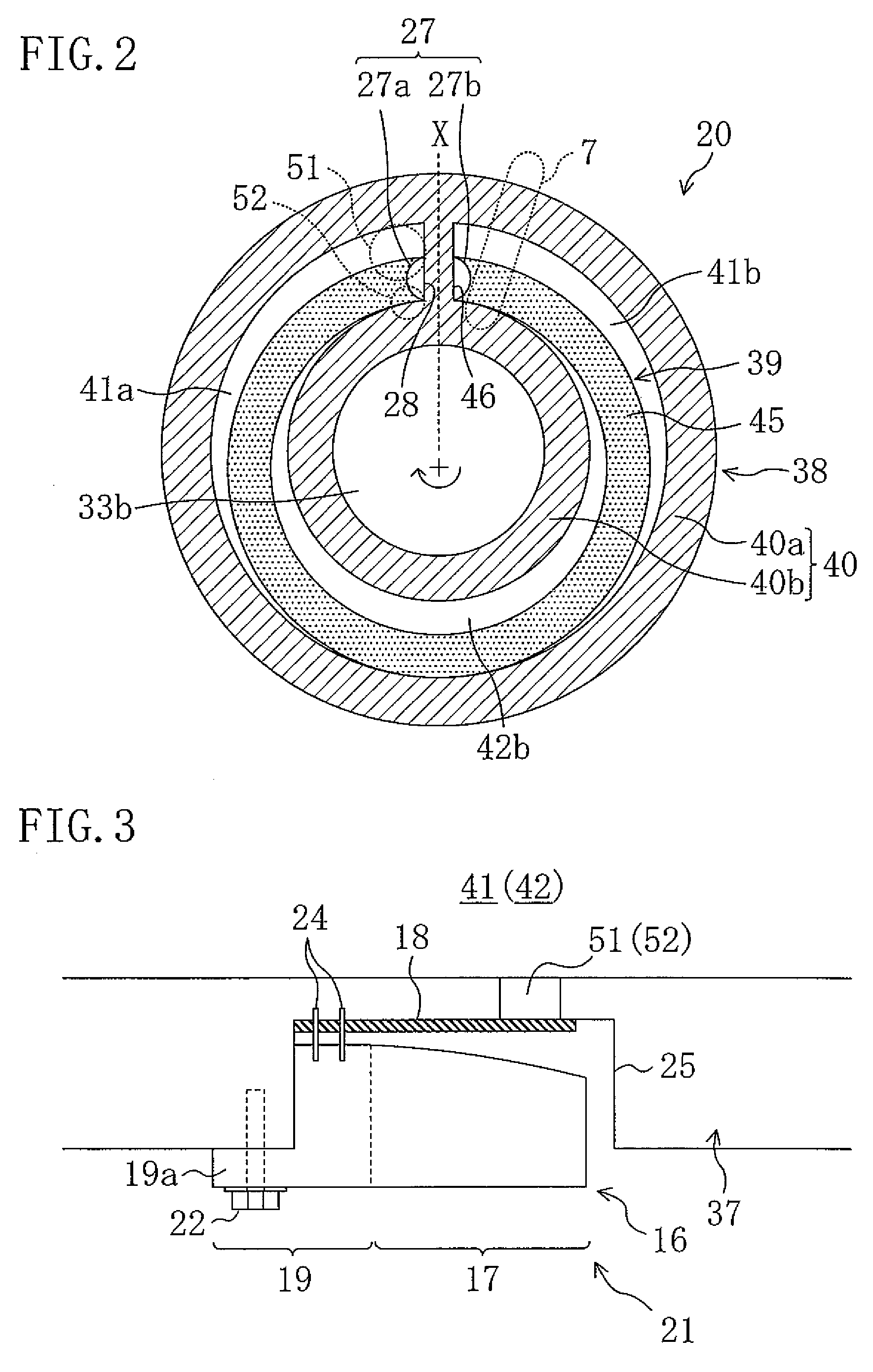
[0043]A first embodiment of the present invention is now described. Referring to FIG. 1, there is shown a longitudinal cross sectional view of a compressor (10) of the first embodiment. The compressor (10) of the first embodiment is a compressor of the rotary type in which the refrigerant in a cylinder chamber (41, 42) is compressed by relative eccentric rotation motion between a ring-shaped piston (45) and a cylinder (40) both of which will be hereinafter described. The rotary type compressor (10) is installed in a refrigerant circuit of a refrigeration apparatus which is charged with carbon dioxide as a refrigerant and which performs a vapor compression refrigeration cycle. The rotary type compressor (10) compresses refrigerant drawn in from the evaporator and then discharges it to the condenser. In this refrigerant circuit, the high pressure of the refrigeration cycle becomes equal to or higher than the critical pressure of carbon dioxide. Also note that the rotar...

second embodiment

of the Invention

[0084]A second embodiment of the present invention is now described. Referring to FIG. 6, there is shown a longitudinal cross sectional view of a compressor (10) of the second embodiment. This compressor (10) is a rotary type compressor (10) of the scroll type which is configured to compress refrigerant in a compression chamber (41) by orbital motion of a movable scroll (38) (to be hereinafter described) against a fixed scroll (39). As in the first embodiment, the compressor (10) of the second embodiment is installed in a refrigerant circuit of a refrigeration apparatus which is charged with carbon dioxide as a refrigerant and which performs a vapor compression refrigeration cycle.

[0085]The compressor (10) has a casing (15) which is a longitudinally long, cylinder-shaped, hermetical container. The casing (15) contains thereinside a compression mechanism (20) and an electric motor (30) wherein the compression mechanism (20) is positioned nearer the upper side while th...

third embodiment

of the Invention

[0105]A third embodiment of the present invention is now described below. Referring to FIG. 9, there is shown a longitudinal cross section of a compressor (10) of the third embodiment. The compressor (10) is a rotary type compressor (10) of the swinging type in which refrigerant in a compression chamber (41) is compressed by swinging motion of a piston (45) (hereinafter described) within a cylinder (40). The compressor (10) is installed in a refrigerant circuit of a refrigeration apparatus which is charged with carbon dioxide as a refrigerant and which performs a vapor compression refrigeration cycle, as in the first embodiment.

[0106]The compressor (10) has a casing (15) which is a longitudinally long, cylinder-shaped, hermetical container. The casing (15) contains thereinside a compression mechanism (20) and an electric motor (30) wherein the compression mechanism (20) is positioned nearer the lower side while the electric motor (30) is positioned nearer the upper s...


PUM


Abstract

A valve guard for restricting the amount of deformation of a valve disc has a main body part abuttable with the back surface of the valve disc, and a fixation part extending to outside of a receding part. Upon mounting the valve guard to an end plate part, the fixation part is firmly attached to the outside of the receding part of the end plate part.

Description

CROSS-REFERENCE TO RELATED APPLICATIONS[0001]This U.S. National stage application claims priority under 35 U.S.C. §119(a) to Japanese Patent Application No. 2005-122736, filed in Japan on Apr. 20, 2005, the entire contents of which are hereby incorporated herein by reference.TECHNICAL FIELD[0002]The present invention relates to rotary type compressors configured to compress a fluid in a compression chamber composed of a movable member and a fixed member.BACKGROUND ART[0003]Rotary type compressors have been known in the past in which the discharge valve, for opening and closing a discharge passage in fluid communication with a compression chamber, is formed using a reed valve. This type of discharge valve is made up of a valve disc of plate shape and a valve guard for restricting the amount of deformation of the valve disc, and is set on the back surface side of an end plate part whose front surface faces the compression chamber. The valve disc is disposed along the back surface of t...

Claims


Application Information

Patent Timeline
Patent Type & Authority Patents(United States)
IPC IPC(8): F04B17/00F16K15/16
CPCF04C18/045F04C18/322F04C29/128F04C18/02F04C18/0215F04C18/3564F04C23/008Y10T137/7892
Inventor SHIMIZU, TAKASHISHIBAMOTO, YOSHITAKAFURUSHO, KAZUHIROHORI, KAZUTAKASOTOJIMA, TAKAZOMASUDA, MASANORI
Owner DAIKIN IND LTD
Learn More