
Device for controlling a heat engine starter, such as that of a motor vehicle, and starter comprising one such device

a technology for starters and motor vehicles, which is applied in the direction of engine starters, dynamo-electric converter control, electric generator control, etc., can solve the problems of accidental ‘sticking’ of moving contacts, the risk of degradation of the movement transmission device acting between the electric motor of the starter and the output shaft, etc., to prevent the possibility of resetting the computer installed on the vehicle, prevent the effect of premature wear of brushes and less battery voltage drop

Inactive Publication Date: 2010-09-28
VALEO EQUIP ELECTRIC MOTEUR
View PDF10 Cites 10 Cited by
  • Summary
  • Abstract
  • Description
  • Claims
  • Application Information

AI Technical Summary

Benefits of technology

[0039]Degradation of the movement transmission device acting between the electric motor of the starter and the output shaft, such as the crankshaft, of the thermal engine, is avoided.
[0040]The movement transmission device comprising a toothed starting ring, shaving of the starting ring by the pinion of the starter head is thus prevented.
[0041]Premature wear to the brushes is also prevented, as well as accidental sticking of the contacts.
[0042]The voltage drop in the battery is less so that resetting of the computers installed on board the vehicle is avoided, in particular resetting of the computer controlling the thermal engine.
[0047]The service life of the starter is in general terms increased along with its reliability.
[0050]In this case, in one embodiment, a freewheel device is for example provided at the driving pulley or the driving sprocket wheel so that wear on the movement transmission device is minimised.

Problems solved by technology

In general terms this current and torque peak gives rise to a risk of degradation of the movement transmission device acting between the electric motor of the starter and the output shaft, such as the crankshaft of the thermal engine.
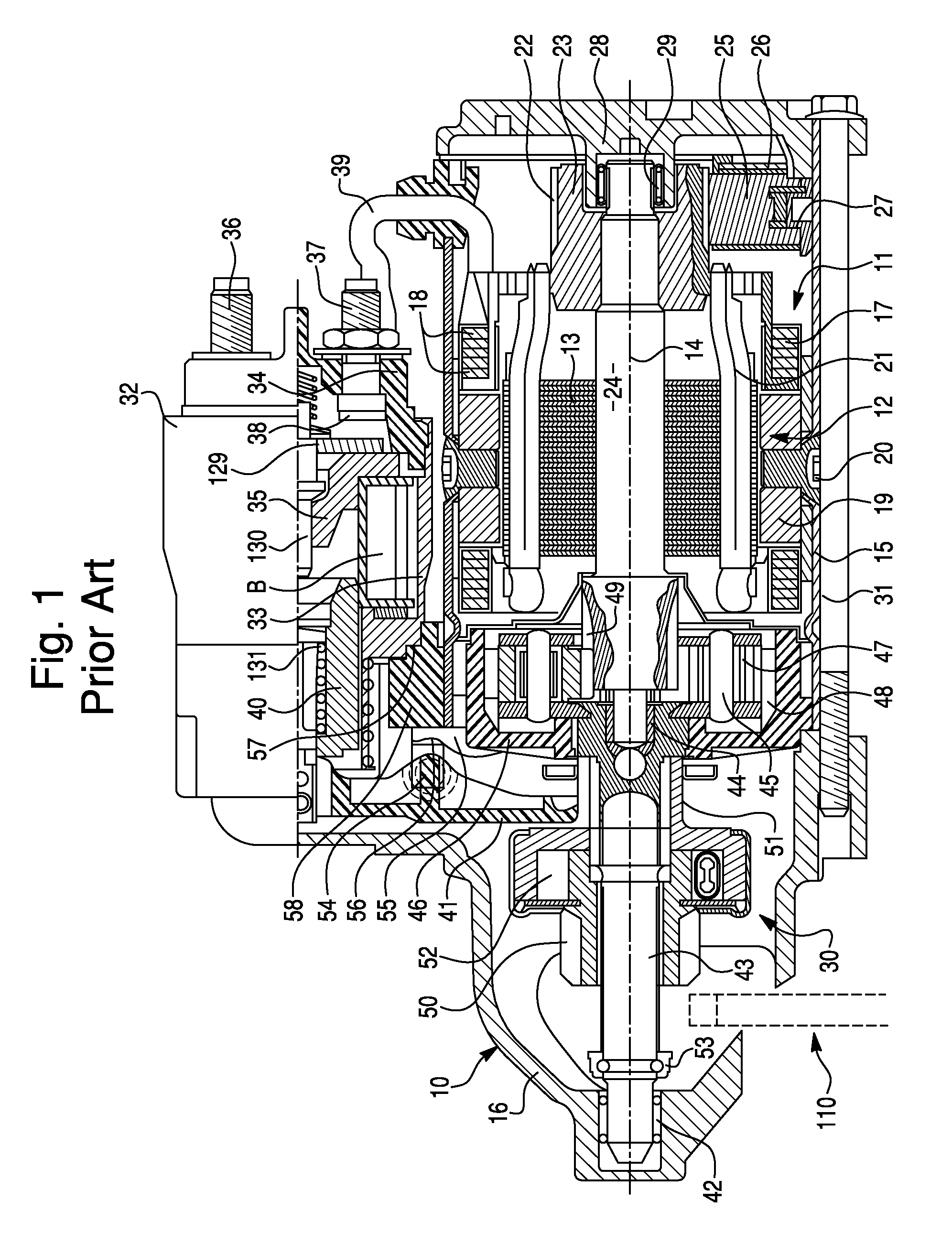
In addition, there is a risk of accidental ‘sticking’ of the moving contact 129 to the fixed contacts 38.

Method used


Image

  • Device for controlling a heat engine starter, such as that of a motor vehicle, and starter comprising one such device
  • Device for controlling a heat engine starter, such as that of a motor vehicle, and starter comprising one such device
  • Device for controlling a heat engine starter, such as that of a motor vehicle, and starter comprising one such device

Examples


Embodiment Construction

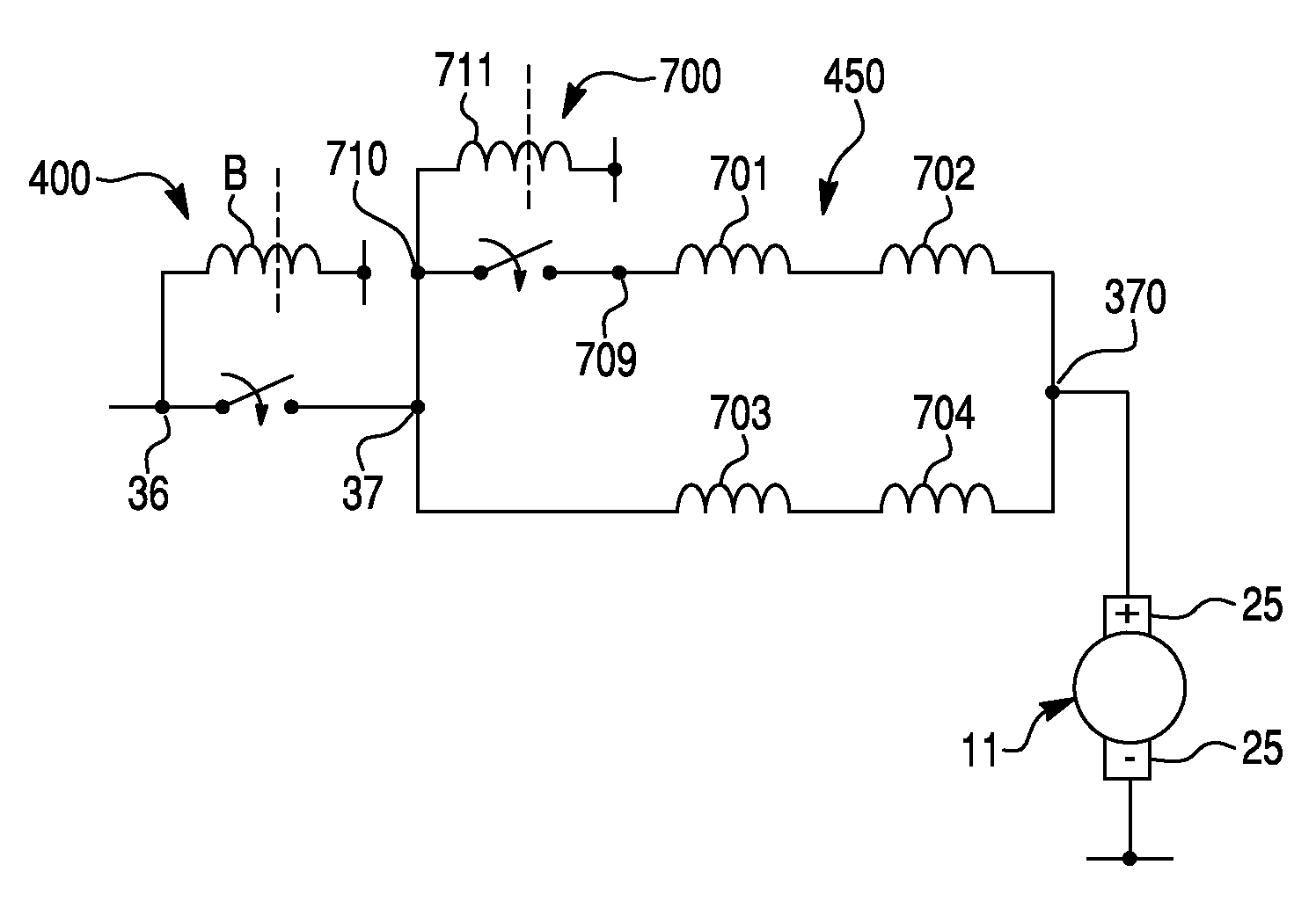
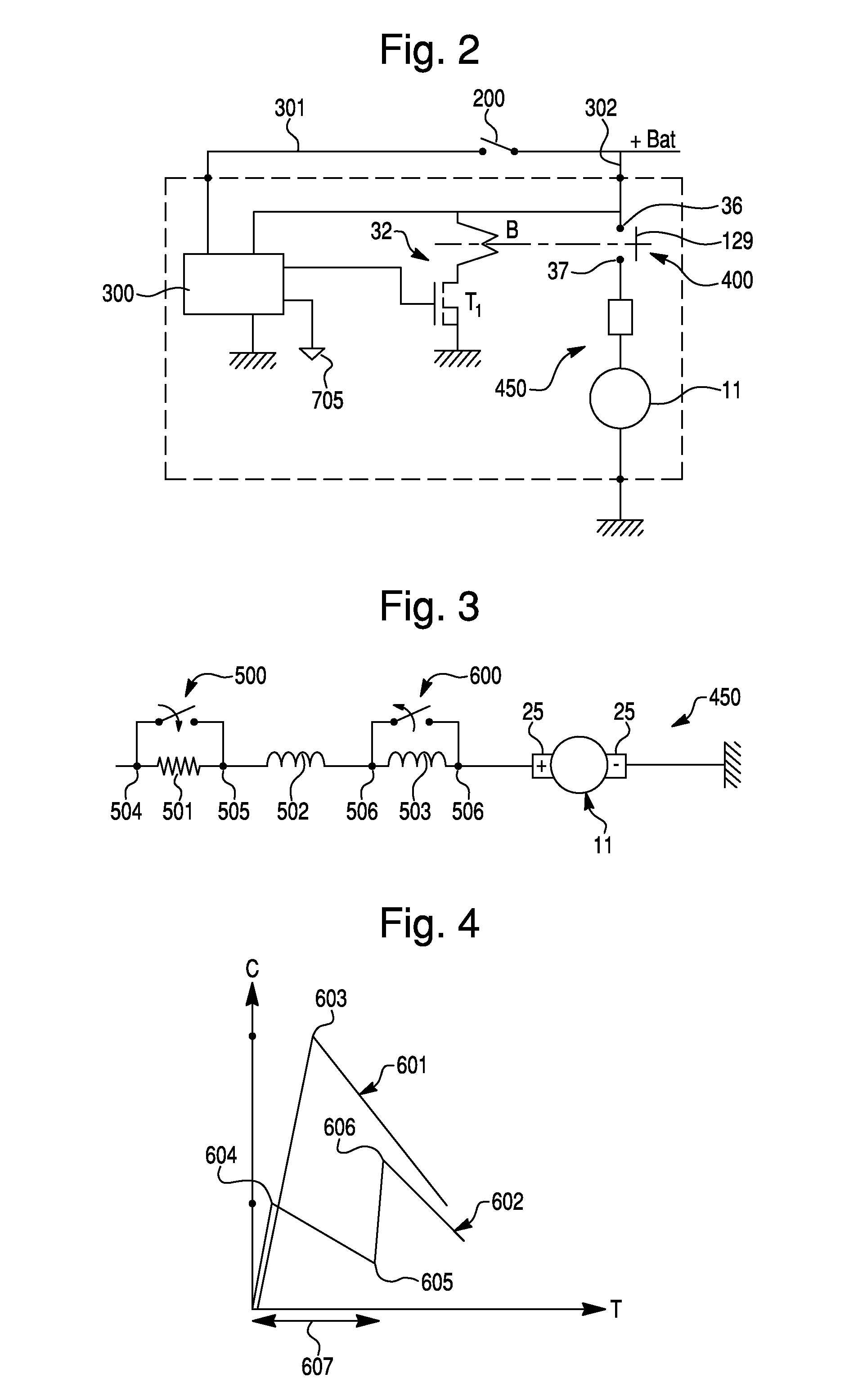
[0059]In FIGS. 2 to 6 the elements common with or similar to those in FIG. 1 will be allocated the same reference numbers.

[0060]The control device for a starter for a thermal engine, in particular for a motor vehicle thermal engine, provided with an electric motor with a field coil and an armature coil connected in series via brushes shown symbolically in FIGS. 3 and 5, comprises as in FIG. 1 a power contact and at least one supplementary contact or switch with time-delayed control, that is to say deferred action.

[0061]This switch fulfils the role of auxiliary switch.

[0062]The power contact 400 is here of the type in FIG. 1 and therefore has recourse (FIG. 2) to an electromagnetic contactor 32 comprising an excitation coil B with one or two windings, activated by a starting switch 200 connected to the positive terminal (+Bat) of a battery. The closure of the staring switch 200, closed for example by an ignition key or by a starting card of the motor vehicle, allows the electrical su...


PUM


Abstract

The invention relates to a device for controlling a starter for a heat engine that is equipped with an electric motor having a field coil with several windings and an armature winding, both of which are mounted in series, comprising a power contact which is equipped with terminals, one of said terminals being connected to the positive terminal (+Bat) of a battery and the other terminal being connected to the field coil having several windings. The inventive device comprises first means which, in a first phase upon closure of the power contact, activate part of the windings of the field coil and second delayed-action means which, in a second phase during which the power contact is always closed, activate at least a large number of the windings of the coil. The invention is intended for the heat engine starter of a vehicle.

Description

TECHNICAL FIELD OF THE INVENTION[0001]The invention relates to a device for controlling a thermal engine starter, in particular for a motor vehicle, comprising an electric motor provided with a field winding and an armature winding connected in series.PRIOR ART[0002]With reference to FIG. 1, a conventional starter 10 comprises a support 16, intended to be fixed to a fixed part of the motor vehicle and fixedly carrying on the one hand the casing 15 of an electric motor 11 and on the other hand the housing 33 of an electromagnetic contactor 32 extending parallel to and radially above the electric motor 11 provided with a shaft 24.[0003]The starter also comprises a starter head 30 provided with a freewheel device 52 acting between a pinion 50 and a driver 51, an output shaft 43 whose axis is merged with the axis 14 of the shaft 24, and a pivoting control lever 41 acting between a movable core 40 that the contactor 32 has and the driver 51 of the starter head 30.[0004]In FIG. 1 the devi...

Claims


Application Information

Patent Timeline
Patent Type & Authority Patents(United States)
IPC IPC(8): F02N11/00
CPCF02N11/0859F02N11/087Y10T74/131F02N2300/102F02N11/08F02N11/00
Inventor LABBE, NICOLASMORNIEUX, CHRISTIAN
Owner VALEO EQUIP ELECTRIC MOTEUR
Learn More