System and method for encoding information in magnetic stripe format for use in radio frequency identification transactions

a technology of magnetic stripe and information, applied in the field of system and method for completing a transaction, can solve problems such as unnecessary overhead, and achieve the effect of reducing costs

Inactive Publication Date: 2010-09-28
LIBERTY PEAK VENTURES LLC
View PDF673 Cites 245 Cited by
  • Summary
  • Abstract
  • Description
  • Claims
  • Application Information

AI Technical Summary

Benefits of technology

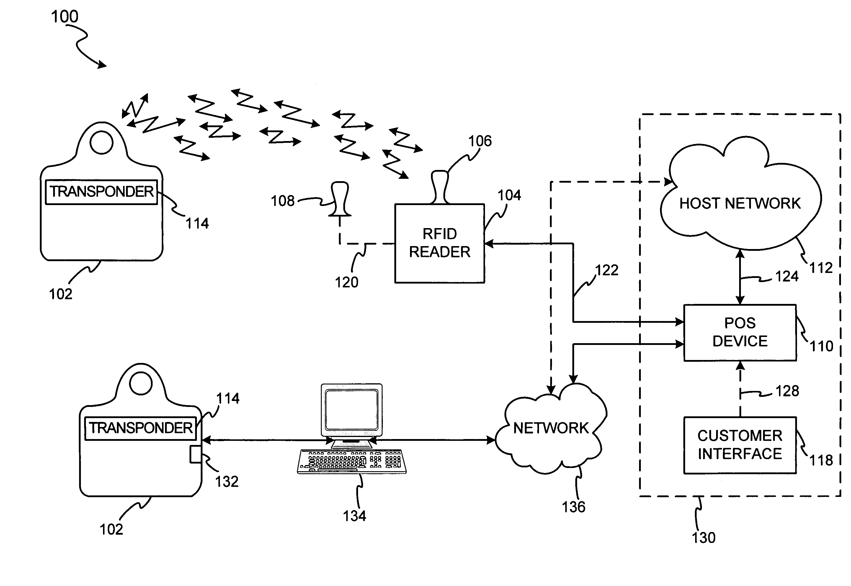
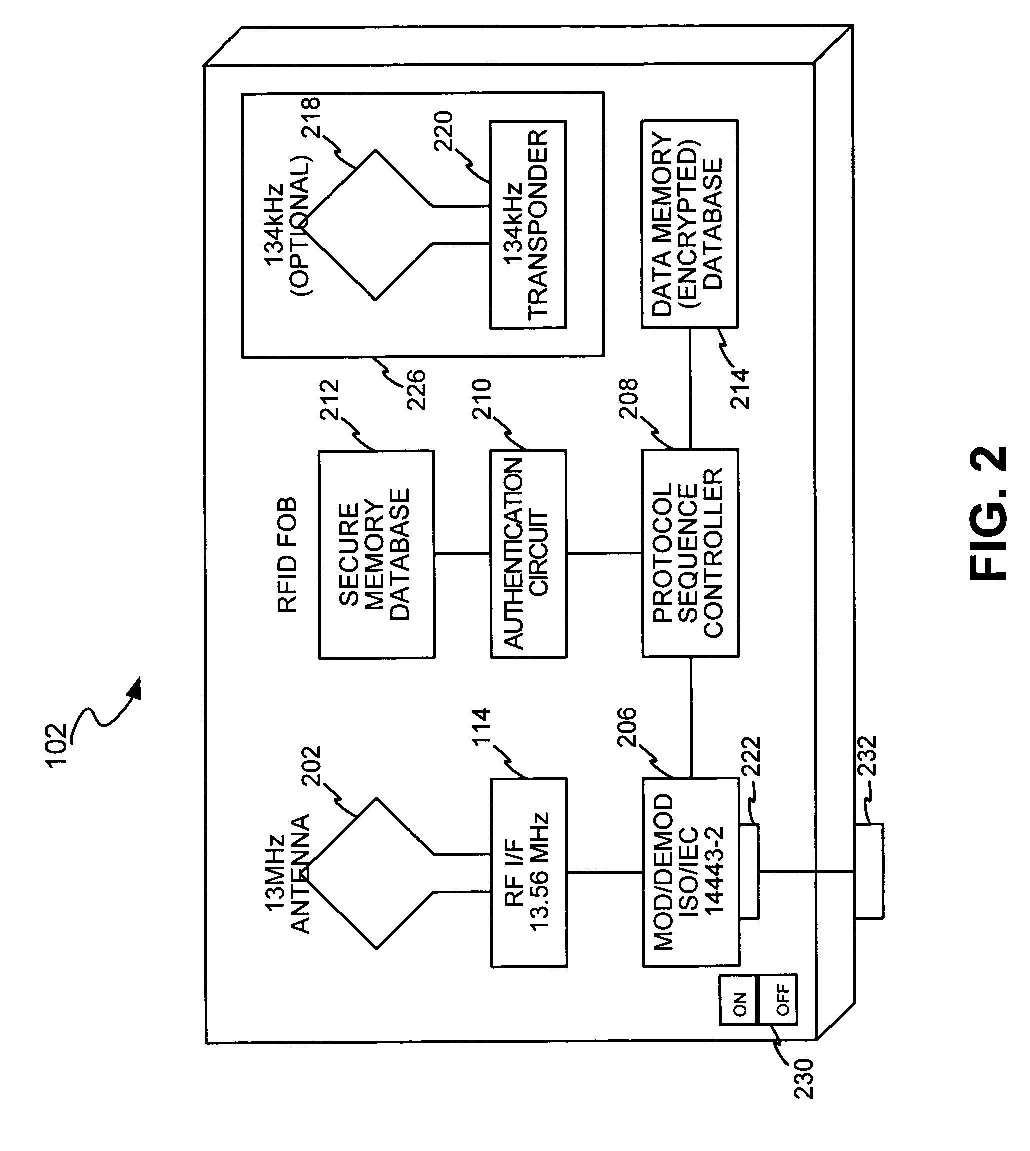
[0012]The proxy account identifier may take the form of any suitable data transmission which is recognizable by the merchant system. That is, the merchant system does not detect that the proxy account identifier includes only partial account information. This is true because the invention includes the partial account information in any traditional account information format. For example, if the merchant system is configured to receive information in magnetic stripe format, the proxy account identifier is provided to the merchant system in magnetic stripe format. As such, the present invention is more advantageous than conventional fob devices in that the proxy transaction account identifier does not have to be sent to a third-party authorizing entity for correlation to a customer number formatted in magnetic stripe which may then be sent to a merchant system for processing. The present invention eliminates the cost associated with involving a third-party server to translate the account fob data into a merchant recognizable format (e.g., magnetic stripe).

Problems solved by technology

In this way, the conventional transaction processing method involves an indirect path which causes undue overhead due to the use of the third-party server to correlate the fob identification data to a customer account prior to providing the accompanying transaction request to the merchant POS for completion.

Method used


Image

  • System and method for encoding information in magnetic stripe format for use in radio frequency identification transactions
  • System and method for encoding information in magnetic stripe format for use in radio frequency identification transactions
  • System and method for encoding information in magnetic stripe format for use in radio frequency identification transactions

Examples


Embodiment Construction

[0031]The present invention may be described herein in terms of functional block components, screen shots, optional selections and various processing steps. Such functional blocks may be realized by any number of hardware and / or software components configured to perform to specified functions. For example, the present invention may employ various integrated circuit components (e.g., memory elements, processing elements, logic elements, look-up tables, and the like), which may carry out a variety of functions under the control of one or more microprocessors or other control devices. Similarly, the software elements of the present invention may be implemented with any programming or scripting language or platforms such as C, C++, Java, JavaCard applets, MULTOS Executive Language, COBOL, assembler, PERL, extensible markup language (XML), JavaCard and MULTOS with the various algorithms being implemented with any combination of data structures, objects, processes, routines or other progr...


PUM


Abstract

A transaction device system is associated with a transaction device proxy account identifier, which may be stored in a database on the transaction device system and may be associated with a transaction account identifier for use in completing a transaction. The proxy transaction device identifier may include at least a first portion which corresponds to a portion of the transaction device identifier. The first portion of the proxy transaction device identifier may be segmented into proxy fields where a first segment includes a portion of a transaction account data set, and a second segment has encoded therein an account provider desired information. The proxy account identifier segments are undetectable by receiving systems such that the proxy account identifier emulates a merchant recognizable data transfer format. The account provider system uses the first portion of the transaction device identifier to reassemble the transaction device identifier for use in transaction completion.

Description

RELATED APPLICATIONS[0001]This invention is a continuation-in-part of, and claims priority to U.S. patent application Ser. No. 10 / 192,488, entitled “SYSTEM AND METHOD FOR PAYMENT USING RADIO FREQUENCY IDENTIFICATION IN CONTACT AND CONTACTLESS TRANSACTIONS,” filed on Jul. 9, 2002 now U.S. Pat. No. 7,239,226 (which itself claims priority to U.S. Provisional Patent Application No. 60 / 304,216, filed Jul. 10, 2001), and is also a continuation-in-part of and claims priority to U.S. patent application Ser. No. 10 / 340,352, entitled “SYSTEM AND METHOD FOR INCENTING PAYMENT USING RADIO FREQUENCY IDENTIFICATION IN CONTACT AND CONTACTLESS TRANSACTIONS,” filed Jan. 10, 2003 (which itself claims priority to U.S. Provisional Patent Application No. 60 / 396,577, filed Jul. 16, 2002), all of which are incorporated herein by reference.FIELD OF INVENTION[0002]This invention generally relates to a system and method for completing a transaction, and more particularly, to completing a transaction using a p...

Claims


Application Information

Patent Timeline
Patent Type & Authority Patents(United States)
IPC IPC(8): G06Q20/00G07C9/00
CPCG06Q20/00G06Q20/04G06Q20/0855G06Q20/10G06Q20/14G06Q20/327G06Q20/3674G06Q30/0633G07C9/00111G07C9/00119G07C9/28G07C9/29
Inventor BERARDI, MICHAEL J.BLIMAN, MICHALBONALLE, DAVID S.SAUNDERS, PETER D.
Owner LIBERTY PEAK VENTURES LLC
Why Eureka
Try Eureka